

Transformerless : Which is a better circuit?
 william chan
Posts: 1,326
william chan
Posts: 1,326
I need some help here.
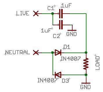
1. Which circuit will supply more DC current to the load?
2. Which circuit will have less ripples at the load?
3. Which circuit is less stressful on the diodes and capacitors?
4. Which circuit is more energy efficient?
Thanks a million.
▔▔▔▔▔▔▔▔▔▔▔▔▔▔▔▔▔▔▔▔▔▔▔▔
www.fd.com.my
www.mercedes.com.my
1. Which circuit will supply more DC current to the load?
2. Which circuit will have less ripples at the load?
3. Which circuit is less stressful on the diodes and capacitors?
4. Which circuit is more energy efficient?
Thanks a million.
▔▔▔▔▔▔▔▔▔▔▔▔▔▔▔▔▔▔▔▔▔▔▔▔
www.fd.com.my
www.mercedes.com.my
355 x 317 - 13K
468 x 267 - 14K
Comments
Get a·fused "variac".
Post Edit -- A Fluke "Scopemeter" would be excellent, but a standard bench 'scope powered via an isolation transformer would be an equally acceptable·alternative.
Post Edited (PJ Allen) : 5/10/2008 1:46:56 PM GMT
Q1- depends on the components used, but half-wave rectifiers are ususally only used up to 1W
Q2- both will have nothing but ripples, however, at this point in the ckt the more ripples the higher the final voltage.
Q3- select the proper components
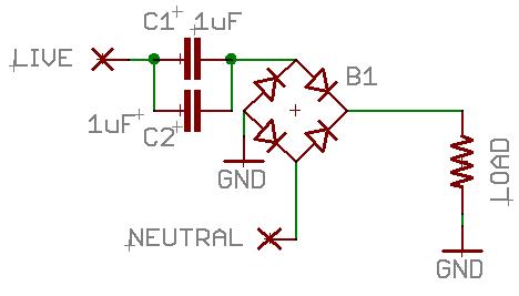
Q4- full wave, bridge ckt 2
Take a look at this-
http://www.play-hookey.com/ac_theory/ps_rectifiers.html
I have tested both circuits, they both work to a certain extend.
But they both have strengths and weaknesses.
That's why I want to know which is better.
You usually have all the answers, that's the reason why you are called "Counsel of Despair" right?
jmalaysia,
Which state are you from?
I think both circuits are full-wave.
I do agree that circuit 1 looks dangerous, but it actually works if you study it carefully.
The load can be a simple bicycle light bulb.
One last question,
5. Which circuit has less starting current surge?
▔▔▔▔▔▔▔▔▔▔▔▔▔▔▔▔▔▔▔▔▔▔▔▔
www.fd.com.my
www.mercedes.com.my
The "no transformer" part makes it all a bit tricky, since in reality neutral is bonded to ground in a breaker box, making them electrically common. I can only assume you are wanting to plug this into an outlet. Or maybe I am looking at it all wrong.
What kind of output did you get when you tested them?
The cap between 'Live' and 'Gnd' I can barely understand, but the other, which is connected in series... It'll remove any DC component created by the first cap.
(It's a few years since the last time I fiddled with analog and power circuits, though)
The second...
Yes, it's a full wave, yes, but why are the caps before the bridge-rectifier?
(Most designs have it after the rectifier)
▔▔▔▔▔▔▔▔▔▔▔▔▔▔▔▔▔▔▔▔▔▔▔▔
Don't visit my new website...
Yes, I plug it in to a 240v AC outlet and it supplies about 80mA to the load.
Gadgetman,
The capacitors are not there to filter the ripples. They are rated at 400v.
They are there to reduce the current to the load.
Imagine a 6v bulb connected directly to 240v AC, it will explode.
But both these circuits can make it light up correctly, without a transformer.
It is amazing that simple circuits like these 2 can create so much complication. [noparse];)[/noparse]
▔▔▔▔▔▔▔▔▔▔▔▔▔▔▔▔▔▔▔▔▔▔▔▔
www.fd.com.my
www.mercedes.com.my
▔▔▔▔▔▔▔▔▔▔▔▔▔▔▔▔▔▔▔▔▔▔▔▔
www.fd.com.my
www.mercedes.com.my
Leon
▔▔▔▔▔▔▔▔▔▔▔▔▔▔▔▔▔▔▔▔▔▔▔▔
Amateur radio callsign: G1HSM
Suzuki SV1000S motorcycle
Gnd is floating, not earth.
▔▔▔▔▔▔▔▔▔▔▔▔▔▔▔▔▔▔▔▔▔▔▔▔
www.fd.com.my
www.mercedes.com.my
This is indeed a somewhat mind-boggling circuit. I'm thinking a bit about efficiency and where that power is going at the moment, but what I can tell you is that it has horrible power factor (probably doesn't matter to you, because they usually don't charge residential accounts for low power factor, but i wouldn't use this for a commercial product).
If energy is indeed lost in this circuit, it's probably lost from I2R heating in the wiring. It's also possible that you've basically created a rudimentary switched capacitor "regulator" (though it obviously doesn't actually regulate DC)
The inrush current is effectively limited by the load (the light bulb), ignoring the diodes.
I've ignored a whole bunch of components (diodes, and the capacitor to the virtual ground in schematic 2), but hopefully that'll get you started
Circuit #2 is just an ordinary bridge rectifier with a 0.5uF series capacitive impedance producing a voltage drop. In this case, there's no filtering provided since the capacitors are on the AC side of the circuit.
Given cheap high voltage diodes with ratings at 600V or higher, I wouldn't worry too much about stresses on them. Similarly, 1uF capacitors with ratings of 600V are readily available for about $5. More important would be some kind of surge protection on the input. On a 240V line, it's easy to get spikes well in excess of 600V from lightning or switching transients elsewhere on the line.
D1 returns the neg half of 240 to neutral.· That leaves approx 75v "dc" at the load.· The load drops 6vdc at .08A,· which leaves D3 to return the remaining voltage to neutral.· However,· that would be a little over 5W,· which exceeds it's capacity.· That's where C1 and C2 come in (maybe??).· C1's charge path includes the load.· C2 is in parallel with C1/Load,· which means their charge/discharge cycles will be out of phase,· reducing the effective voltage.·· That's the only way I can think of to account for the excess voltage.
Isn't there an easier way to run a 6v bulb??
Sometimes the load could be some superbright LEDs, that's why the diodes are required.
The only other way to power a small load would be using a transformer, which is getting more expensive due to increasing copper prices.
@Mike,
Isn't "2 half wave" equivalent to a "full wave" ?
Are you sure circuit 2 will provide double the current?
I tested the 1st circuit overnight using a pair of China 1uF 400v Metalized Film Capacitors but they exploded after 24 hours.
Any ideas why they exploded?
▔▔▔▔▔▔▔▔▔▔▔▔▔▔▔▔▔▔▔▔▔▔▔▔
www.fd.com.my
www.mercedes.com.my
For the full wave circuit, you have the ripples in phase at twice the frequency and roughly twice the current.
2) I don't know how much current the capacitors are conducting, so I don't know how much heating is going on.
In addition, 400V is less than twice the applied voltage. It wouldn't take much in the way of noise or other spikes on top of the 240V to
exceed the rating of the capacitor. I'd use no less than 600V plus some kind of varistor or other limiter on the input to this supply.
I would like to dispute that "the ripples are out of phase" for the 1st circuit.
I think the 1st circuit will also provide ripples at twice the original ac frequency,
since the bottom half of the original wave is also rectified to become a top wave.
The current flow through the load is about 80mA (averaged), so it's about 40mA per capacitor.
Is it too high for a metalized film capacitor?
▔▔▔▔▔▔▔▔▔▔▔▔▔▔▔▔▔▔▔▔▔▔▔▔
www.fd.com.my
www.mercedes.com.my
I think this really only works well for low current applications.
Post Edited (Agent420) : 5/12/2008 2:31:36 PM GMT
http://ww1.microchip.com/downloads/en/AppNotes/00954A.pdf
For example, a 600v DC capacitor might only be rated at 275v AC. Seems a bit confusing.
Most China capacitors do not mention an AC voltage rating.
▔▔▔▔▔▔▔▔▔▔▔▔▔▔▔▔▔▔▔▔▔▔▔▔
www.fd.com.my
www.mercedes.com.my