

Inductor Size for BasicStamp in Automotive application
 David H.
Posts: 78
David H.
Posts: 78
Hi there,
I'm working on an application using the basic stamp 1 in a vehicle.· It will control the sequencing of the taillights with 3 LED taillight bulbs on each side.· I believe I should an inductor inline to stabilize the Stamp.· Are there any recommendations for the size of Inductor?
Thank you for any and all help.
▔▔▔▔▔▔▔▔▔▔▔▔▔▔▔▔▔▔▔▔▔▔▔▔
David
There are 10 types of people in this world,...
Those that understand binary numbers, and those that don't!!!
Post Edited (David H.) : 5/8/2008 1:40:13 AM GMT
668 x 561 - 59K
Comments
▔▔▔▔▔▔▔▔▔▔▔▔▔▔▔▔▔▔▔▔▔▔▔▔
David
There are 10 types of people in this world,...
Those that understand binary numbers, and those that don't!!!
All the inductor does is prevent the current flowing through it from changing as fast as it could without the inductor. You may also need a 10 uF capacitor near the BS1 in order to filter out voltage spikes -- you probably need both the inductor and the capacitor, in other words.
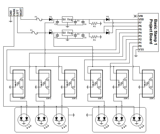
Thank you for a little insight. I uploaded the schematic. I'm using solid state type relays to control the LED taillight bulbs. I used to have the inductor inline after each fuse on the input lines. I believe if I put the inductor back in, and then run power before the inductor to power the relays should work. I think the inductor must of limited the power surge required to light the bulbs properly.
▔▔▔▔▔▔▔▔▔▔▔▔▔▔▔▔▔▔▔▔▔▔▔▔
David
There are 10 types of people in this world,...
Those that understand binary numbers, and those that don't!!!
I'm curious why you think that an inductor will solve your problem. A simple diode-capacitor filter should be plenty to ward off a noisy voltage supply and stabilize the Stamp.
▔▔▔▔▔▔▔▔▔▔▔▔▔▔▔▔▔▔▔▔▔▔▔▔
Beau Schwabe
IC Layout Engineer
Parallax, Inc.
I thought an inductor should be used from reading previous postings. So the diode, and capacitors that I have in the schematic along with the voltage regulator should be all I would need for an automotive situation?
▔▔▔▔▔▔▔▔▔▔▔▔▔▔▔▔▔▔▔▔▔▔▔▔
David
There are 10 types of people in this world,...
Those that understand binary numbers, and those that don't!!!
Observe polarity, and place a cap (470uF or so) directly across VDD and VSS on the Stamp, and yes that should be all that is necessary.
▔▔▔▔▔▔▔▔▔▔▔▔▔▔▔▔▔▔▔▔▔▔▔▔
Beau Schwabe
IC Layout Engineer
Parallax, Inc.
Thank you VERY much. This will make things a little easier.
I really appreciate your replies.
▔▔▔▔▔▔▔▔▔▔▔▔▔▔▔▔▔▔▔▔▔▔▔▔
David
There are 10 types of people in this world,...
Those that understand binary numbers, and those that don't!!!