

12V Load Control
 cah
Posts: 4
cah
Posts: 4
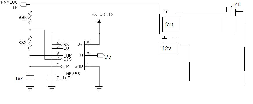
I found a simple way to monitor voltage between 5-16V at this site http://www.bobblick.com/techref/projects/a2d555/a2d555.html·using a 556 timer from Radio Shack so I decided to try load controlling.
I am having some trouble with certain loads in the following setup using a STAMP and a IRF510 Power MOSFET.· It seems that a 12v LED light @ 200ma·can be switched between 11-13v·great, but a fan @ 400ma not so great.· The STAMP will loop a couple of times then stops debugging but the load continues.· Is the fan causing noise that can be filtered?
HIGH 1
start:
DO
V1· VAR Word
V2· VAR Word
V3· VAR Word
V4· VAR Word
PULSIN 5,1,V2
V1=21816
V4=V1/V2
V3=V4*100 'I am going to get around the integer-only Stamp math.
V4=V2*V4
V1=V1-V4*10 'remember the Stamp has left-to-right math
V4=V1/V2
V3=V4*10+V3
V4=V2*V4
V1=V1-V4*10
V4=V1/V2
V3=V4+V3
V3=V3+260 '250 is really 2.5 volts
DEBUG "Voltage = ",DEC V3,CR 'we get a reading in hundredths of volts
DEBUG CLREOL
PAUSE 2000
LOOP UNTIL (V3<1100)
LOW 1
DO
PULSIN 5,1,V2 'I used pin 0
V1=21816
V4=V1/V2
V3=V4*100 'I am going to get around the integer-only Stamp math.
V4=V2*V4
V1=V1-V4*10 'remember the Stamp has left-to-right math
V4=V1/V2
V3=V4*10+V3
V4=V2*V4
V1=V1-V4*10
V4=V1/V2
V3=V4+V3
V3=V3+260 '250 is really 2.5 volts
DEBUG "Voltage = ",DEC V3,CR 'we get a reading in hundredths of volts
DEBUG CLREOL
PAUSE 2000
LOOP UNTIL (V3>1300)
GOTO start
872 x 360 - 22K
Comments
······························· Take a look at this post this might help you
·http://forums.parallax.com/showthread.php?p=625984··· ·
▔▔▔▔▔▔▔▔▔▔▔▔▔▔▔▔▔▔▔▔▔▔▔▔
··Thanks for any·
·
·
·
·
Sam
Post Edited (sam_sam_sam) : 4/23/2008 12:03:31 AM GMT