

Controlling source voltage with a BS1
 Garth
Posts: 18
Garth
Posts: 18
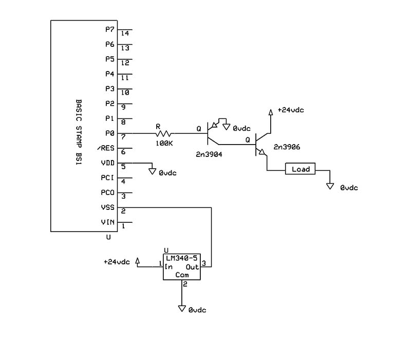
Ok, I'm still new at this. I need to send source voltage to my load. I've got it working (see schematic) but I can't help thinking there is a more efficient way to accomplish this.
Any ideas and comments are welcome.
Thanks
Any ideas and comments are welcome.
Thanks
800 x 657 - 43K
Comments
▔▔▔▔▔▔▔▔▔▔▔▔▔▔▔▔▔▔▔▔▔▔▔▔
·"If you build it, they will come."
Thanks again
▔▔▔▔▔▔▔▔▔▔▔▔▔▔▔▔▔▔▔▔▔▔▔▔
·"If you build it, they will come."
·
Since your voltage supplies are different, using a single PNP transistor won’t work.· You need the NPN in this case as a high-side driver.
·
If you can move your load so that it is happy with one side connected to your 24V supply, then a single NPN transistor solution will work.
BTW) In your schematic, it looks as though the Collector and Emitter of the PNP are swapped.
·
·
·
What are the current requirements of your load?·
That will help determine the correct transistor and resistor values at the transistor base that·you should use.
·
▔▔▔▔▔▔▔▔▔▔▔▔▔▔▔▔▔▔▔▔▔▔▔▔
Beau Schwabe
IC Layout Engineer
Parallax, Inc.
The chip itself doesn't even a power pin on it (Only a single ground)...
Wire your load directly to the 24Vdc supply and use this device to control the connection to ground...
As mentioned mentioned, if the load is inductive (like a motor or relay), place a diode across the coil to reduce the "fly back" energy...
Happy Stamping....
Also make sure your positive power is connected to VDD and your ground connected to VSS.
Good luck with the project.
▔▔▔▔▔▔▔▔▔▔▔▔▔▔▔▔▔▔▔▔▔▔▔▔
David
There are 10 types of people in this world,...
Those that understand binary numbers, and those that don't!!!
Note -- These "gates" (having "open collector" outputs) are for sinking current, not sourcing voltage.
Post Edited (PJ Allen) : 4/21/2008 11:21:58 PM GMT
There is a great chip out there by the name:
UDN2981
http://www.datasheetcatalog.com/datasheets_pdf/U/D/N/2/UDN2981.shtml
It is an 8-channel source driver chip.
You have 8 input points that can you put 5 volts into and then you can put 15 volts into the 2981, which in turn drive 15 volts out of each 8 outputs.
Check it out, it might work for you,
Joe
▔▔▔▔▔▔▔▔▔▔▔▔▔▔▔▔▔▔▔▔▔▔▔▔
“Intellectual growth should commence at birth and cease only at death”
Albert Einstein
Thanks kingspud!
Great matching/pairing device to the 2803...
·