

BS2 usage without BOE or Homework Board
 servello
Posts: 113
servello
Posts: 113
Greetings,
Please forgive me if this question seems to be rather simple with an equally simple and obvious answer.
After working through the first 4 chapters of "What's A Microcontroller?" and doing some study of electronics on the side, I thought I'd like to experiment by 'breaking-away' from the 'hand-holding' nature of using the BOE and popping the BS2 into a standalone solderless breadboard.
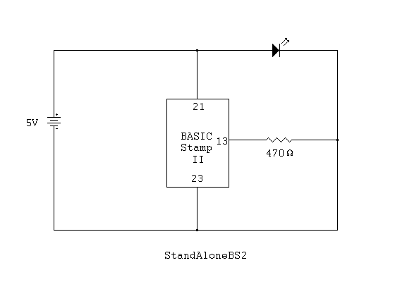
** See·attached photo,·schematic and PBASIC code·**
It seemed pretty straight forward.
On a 5V powered solderless breadboard:
Place a lead from Pin21·(VDD) to the positive (+)·rail
Place a lead from Pin23·(VSS) to the negative (-) rail
Place a resistor (470 ohm)·from Pin13·(I/O) to the positive (+) rail
Place a lead from Pin13 to an unused slot on the board
Place·LED anode leg to that same row
Place LED cathode leg to the negative (-) rail
As can be seen in the photo, it worked out very well.
I, of course had to upload my program to the BS2 to tell it what to do (blink an LED in this case). I did this by my usual method of having the Stamp·placed onto my Board of Education, typing the code into the PBASIC 2.5 Editor and finally uploading the code·to the Stamp (via USB cable).
Then, I had to remove the Stamp and place it into the solderless breadboard to complete my circuit. Needless to say, this would be quite tedious to do each and every time I wanted to try a new circuit.
To save me from doing the above time and time again, I would need a way to have the BS2 remain on the solderless breadboard and have the ability to upload my programs to it.
OK. Now the question (yes, there actually is one ).
).
What I'd like to know is, if·the tool I'm looking for is·the Parallax·USB2SER FTDI FT232BM USB to Serial Development Tool?
http://www.parallax.com/Store/Accessories/Tools/tabid/162/CategoryID/37/List/0/Level/a/ProductID/32/Default.aspx?SortField=ProductName%2cProductName
Any help will be much appreciated.
I made this post as specific as I could·with included attachments and a link·just in case another newcomer might have this same question.
Best,
Dominic
Please forgive me if this question seems to be rather simple with an equally simple and obvious answer.
After working through the first 4 chapters of "What's A Microcontroller?" and doing some study of electronics on the side, I thought I'd like to experiment by 'breaking-away' from the 'hand-holding' nature of using the BOE and popping the BS2 into a standalone solderless breadboard.
** See·attached photo,·schematic and PBASIC code·**
It seemed pretty straight forward.
On a 5V powered solderless breadboard:
Place a lead from Pin21·(VDD) to the positive (+)·rail
Place a lead from Pin23·(VSS) to the negative (-) rail
Place a resistor (470 ohm)·from Pin13·(I/O) to the positive (+) rail
Place a lead from Pin13 to an unused slot on the board
Place·LED anode leg to that same row
Place LED cathode leg to the negative (-) rail
As can be seen in the photo, it worked out very well.
I, of course had to upload my program to the BS2 to tell it what to do (blink an LED in this case). I did this by my usual method of having the Stamp·placed onto my Board of Education, typing the code into the PBASIC 2.5 Editor and finally uploading the code·to the Stamp (via USB cable).
Then, I had to remove the Stamp and place it into the solderless breadboard to complete my circuit. Needless to say, this would be quite tedious to do each and every time I wanted to try a new circuit.
To save me from doing the above time and time again, I would need a way to have the BS2 remain on the solderless breadboard and have the ability to upload my programs to it.
OK. Now the question (yes, there actually is one
).What I'd like to know is, if·the tool I'm looking for is·the Parallax·USB2SER FTDI FT232BM USB to Serial Development Tool?
http://www.parallax.com/Store/Accessories/Tools/tabid/162/CategoryID/37/List/0/Level/a/ProductID/32/Default.aspx?SortField=ProductName%2cProductName
Any help will be much appreciated.
I made this post as specific as I could·with included attachments and a link·just in case another newcomer might have this same question.
Best,
Dominic


Comments
And if they're not in stock, then one of these: http://www.parallax.com/Store/Accessories/CablesConverters/tabid/166/CategoryID/40/List/0/Level/a/ProductID/378/Default.aspx?SortField=ProductName%2cProductName
along with one of these: http://www.parallax.com/Store/Accessories/CablesConverters/tabid/166/CategoryID/40/List/0/Level/a/ProductID/33/Default.aspx?SortField=ProductName%2cProductName
And you'll need to make an adapter to go from the DB-9 to your white-board -- basically a DB-9 F with 4 wires added to it -- 2, 3, 5, and I think 8, and wire 6 and 7 together.
The BS2 programming port wants 'true' RS-232 signal levels -- +- 5 volts to +- 10 volts.· The USB to Serial adapter above does this.· The "FTDI" unit you called out does not.
http://www.parallax.com/Store/Microcontrollers/BASICStampOEM/tabid/135/CategoryID/10/List/0/SortField/0/Level/a/ProductID/21/Default.aspx
or
http://www.parallax.com/Store/Microcontrollers/BASICStampOEM/tabid/135/CategoryID/10/List/0/SortField/0/catpageindex/2/Level/a/ProductID/501/Default.aspx
These both fit very nicely on a standard breadboard and still have the RS-232 attachment (see attached photo of a Basic Stamp 2 OEM in use).
looking at your schematic, you show the LED from +5Vdc (Vcc) to the junction of a resistor to a STAMP output AND GROUND.
While the resistor will protected the STAMP, by the schematic, the LED is across the full 5Vdc.
Remove the link from the junction of the LED and resistor to ground.
I presume that the circuit on the bread board omitted this connection.
I went over all the recommendations and links. All usefull ideas.
For simplicities sake and ease-of-use, I think I'll purchase the Parallax BS2·OEM Module (kit form).
This way I can just pop the module into a circuit and program the Stamp using my existing software setup.
Again, thanks.
-Dominic
-Dominic
As it is, does your LED actually turn on and off? or is it permanently on?
In looking at the photo, it appears that you should remove the blue wire and move the resistor to where the blue wire was.
Then the STAMP output can turn the LED on (HIGH command) and off (LOW command)
See the rough attached part schematic for how the circuit will then be wired and drawn
I think I'm starting to understand, and I'm going to try out your updated circuit.
I'll post the results a little later.
I re-did the circuit as suggested (replaced blue lead wire with the 470 ohm resistor) and it worked great. This circuit is·simpler and more clean (the lesser the components, the better).
Looking at it now, it makes much more sense. I learned a valuable lesson here. Thanks for the help.
- Dominic
It is neat that you are learning this stuff and found this forum to ask questions. I only began a few months ago and the people here CANNOT be beat.
If you haven't why don't you download Parallax's free "What's a Microcontroller?" If you want the printed version, it is inexpensive and well worth it.
--Bill
▔▔▔▔▔▔▔▔▔▔▔▔▔▔▔▔▔▔▔▔▔▔▔▔
You are what you write.
Thanks for joining in on this thread. I have·learned much from reading·your posts here and I look forward to future correspondance. Regarding the "What's a Microcontroller?" material - I think it is simply the best introduction to electronics, programming and circuits there is. I mentioned in my original post that I am currently using the book and have completed the first four chapters.
Best,
Dominic
▔▔▔▔▔▔▔▔▔▔▔▔▔▔▔▔▔▔▔▔▔▔▔▔
- It's just a scratch, but it's a nasty scratch
Thank you very much for the compliment, but I obviously do not deserve it! I should have read your original post more carefully!
I hope you have fun and continue to ask questions of the guys on this forum that actually KNOW something.
--Bill
▔▔▔▔▔▔▔▔▔▔▔▔▔▔▔▔▔▔▔▔▔▔▔▔
You are what you write.
You are too modest. You are a gentleman on these forums and you always do your best to be of help (especially to us real newbies).
I've finished up with the pushbuttons and am now moving along with the servos (I just did the first activity). I do not claim to understand everything from all the past activities, so although I am moving forward, I'm sure I'll be going back to earlier lessons to re-learn the material.
And, as you say, there are always you guys here to help out. And I look forward to future projects and forum participation.
- Dominic
▔▔▔▔▔▔▔▔▔▔▔▔▔▔▔▔▔▔▔▔▔▔▔▔
- It's just a scratch, but it's a nasty scratch