

Reusing my FT232R cable
 oscarc
Posts: 4
oscarc
Posts: 4
Hi all,
I am a programmer, not an electornic engineer so i have a very basic question that haven't solve even browsing the sticky threads.
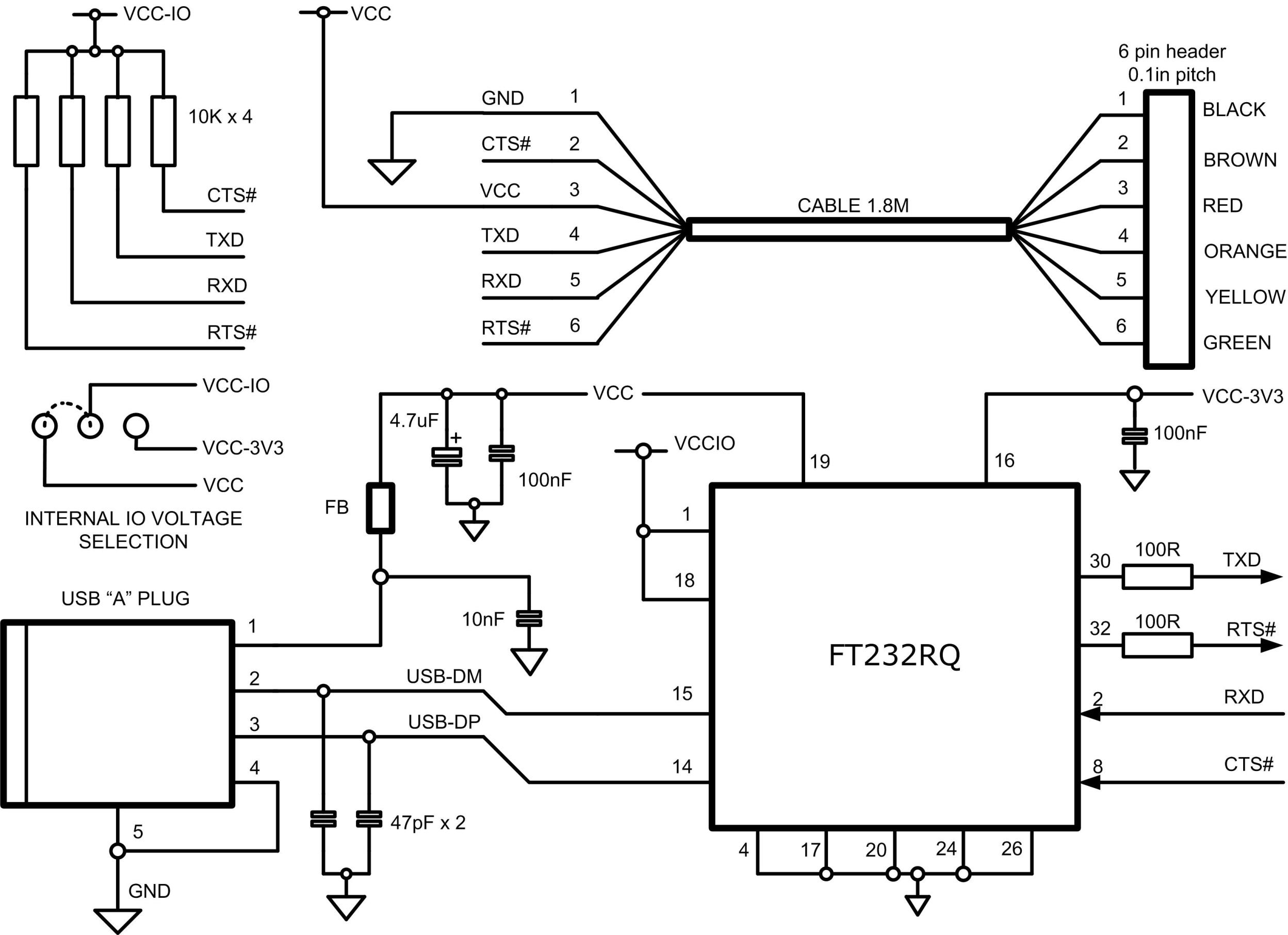
When i was using TTL microcontrollers i purchased some USB to TTL (5v) serial cables form FTDI: http://www.ftdichip.com/Images/ttl232rsch1.jpg
Now i have purchased some P8X32A-40 to experiment with spin and i have no idea on how to reuse·the cables with the propeller.
The connections could be:
·······················
Cable RxD
10K--- P30
Cable TxD
P31
I put a 10K R· on the RxD (for TTL to CMOS) althought·the cable schematic have already one on RxD and other on TxD.
Then for the DTR:
Cable RTS# ---10nF---10K Pull down---NPN---ResetToGround--- RESn
Is this correct?
Thanks in advance?
I am a programmer, not an electornic engineer so i have a very basic question that haven't solve even browsing the sticky threads.
When i was using TTL microcontrollers i purchased some USB to TTL (5v) serial cables form FTDI: http://www.ftdichip.com/Images/ttl232rsch1.jpg
Now i have purchased some P8X32A-40 to experiment with spin and i have no idea on how to reuse·the cables with the propeller.
The connections could be:
·······················
Cable RxD
10K--- P30
Cable TxD
P31
I put a 10K R· on the RxD (for TTL to CMOS) althought·the cable schematic have already one on RxD and other on TxD.
Then for the DTR:
Cable RTS# ---10nF---10K Pull down---NPN---ResetToGround--- RESn
Is this correct?
Thanks in advance?
Comments
Please, i only need a little help. Could some one tell me if this schemtic (in the attachment) is valid to avoid frying my first propeller micro.
Thanks.
Look at the attached GIF for a better schematic. I use such a circuit one year now, without problems.
Andy
Edit: If you can then use DTR instead of RTS, but the IDE can also handle the RTS to produce a Reset.
Post Edited (Ariba) : 4/10/2008 11:01:50 PM GMT
I always try to explicitly indicate where a TX or RX is to or from to avoid such ambiguities.
First of all thaks a lot!
I have several prebuilt cables from FTDI with only TXD, RXD, CTS and RTS signals, so i can't use DTR for the reset.·I will place a switch between RTS and reset to avoid posible comunication problems in normal operation.
My·last doubt now: as in your schematic, no need of using·a serial resistor for RTS, right?
Oscar
·
Right!
If the Transistor gets a 3.3V puls or a 5V puls does not matter for the Propeller.
But if you mean your 10k resistor between the NPN and the Reset: This will not work. The Reset Input has an internal PullUp with ~ 5 kOhm, so a 10k to Ground will never produce a Reset. A 1kOhm will most likely work, to play it save. And then you can also add a seriell resistor in the RXD line (1...4.7k). But both is not really necessary.
Andy
All is clear now. I will try it on the protoboard this afternoon and, with luck, run my first spin code.
Good luck