

Making a guitar: RCTIME & accelerometer, long read
 unlimited
Posts: 9
unlimited
Posts: 9
I'm trying to build a guitar with flex sensors (a variable resistor that goes from 10k to 40k when bent), an accelerometer, a computer,·and the BS2 stamp module.· For now it's NOT going to be real-time; rather send some data to the computer to play notes off that.· I did some forum searching and reading the help and this is what I came up with so far:
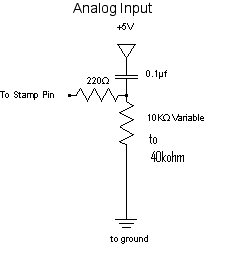
RCTIME (see pic):
Used to select the 'note' to play, currently testing only one 'note' will add more once things work
' {$STAMP BS2}
' {$PBASIC 2.5}
result VAR Word
DO
·HIGH 4
·PAUSE 100
·RCTIME 4, 1, result
·DEBUG ? result
·IF(result > 2000) THEN···· 'RCTIME = 635 *40 *0.1 = 2540
· HIGH 12
· SEROUT 15\12,[noparse][[/noparse]"ON"]
·ELSE
· LOW 12
·ENDIF
LOOP
END
I'm using PIN 4 as the I/O.
My question is will this·make pin 12 high which will make pin 15 output the phrase "ON"?·(I'll·connect·via bluetooth to be interpreted by the computer but dont worry about that part).· Using the 10k to 40k resistor and the 0.1 uF cap, the help says RCTIME = 635 * 10 * .1 = 635 and if it's at 40k then it would be 'RCTIME = 635 *40 *0.1 = 2540... hence the IF(result > 2000)
1 ACCELEROMETER:
Using the code from the Basic stamp startup book with the ADC0834 and same connections:
' {$STAMP BS2}
' {$PBASIC 2.5}
ch0 VAR Byte
ch1 VAR Byte
ch2 VAR Byte
ch3 VAR Byte
checkSum VAR Byte
A2dChipSel PIN 0 ' A/D Converter Chip Select(P0)
A2dDataIn PIN 1 ' A/D Converter Data Input(P1)
A2dClk PIN 2 ' A/D Converter Clock(P2)
A2dDataOut PIN 3 ' A/D Converter Data Output(P3)
A2dMuxId0 CON %1100 ' A/D MUX IDs for Ch 0..3
A2dMuxId1 CON %1110 ' Bit 3 = 1, start bit
A2dMuxId2 CON %1101 ' Bit 2 = 1, single (1)/diff (0)
A2dMuxId3 CON %1111 ' Bit 1 odd / sign, Bit 0 select
a2dMuxId VAR Nib ' A/D Channel MUX ID to shift out
a2dResult VAR Byte ' 8-bit result of A/D conversion
Main:
DO
a2dMuxId = A2dMuxId0 ' Set A/D to convert Ch 0
GOSUB A2D ' Do the conversion
ch0 = a2dResult ' 8-bit result into
· GOSUB Plot_It
LOOP
A2D: ' Initialize signals
HIGH A2dChipSel ' Disable A/D Chip Select
LOW A2dDataIn ' Initial state of data in
LOW A2dClk ' Initial state of clock
a2dResult = 0 ' Clear the 8-bit result
A2D_Start_Conversion: ' Start the conversion process
LOW A2dChipSel ' Enable A/D chip select
A2D_Shift_Out_Channel_ID: ' Shift out the Channel ID value
SHIFTOUT A2dDataIn,A2dClk,MSBFIRST,[noparse][[/noparse]a2dMuxId\4]
A2D_Shift_In_Result: ' Shift in the result
PULSOUT A2dClk,10
SHIFTIN A2dDataOut,A2dClk,MSBPRE,[noparse][[/noparse]a2dResult\8]
HIGH A2dChipSel ' Disable A/D chip select
A2D_End:
· RETURN
Plot_It:
· checkSum = ch0 + ch1 + ch2 + ch3
· DEBUG ch0, ch1, ch2, ch3, checkSum
· PAUSE 250
Plot_It_End:
· RETURN
I'm not sure how to code how I would get the voltage fluctuation from the acc.· Right now the accelerometer output is low,·max 0.08V·and we're getting an·amplifier for it to make it 0.5 or higher.· Ideas? IF(a2dresult > .5) serout etc like in the RCTIME
COMBINE these two:
combine the IF statements together and then do the serout
My question: does this make sense or am·I going to head into a deadend?
230 x 261 - 2K
Comments
' {$STAMP BS2}
' {$PBASIC 2.5}
result VAR Word
DO
HIGH 4
PAUSE 100
RCTIME 4, 1, result
DEBUG ? result
IF(result > 2000) THEN
HIGH 12
SEROUT 15\12,[noparse][[/noparse]"ON"]
ELSE
LOW 12
ENDIF
LOOP
END
I'm using PIN 4 as the I/O and PIN 12 as an indicator of whether PIN 15 outputs ON
Using the 10k to 40k resistor and the 0.1 uF cap, STAMP help says RCTIME = 635 * 10 * .1 = 635 and if it's at 40k then it would be 'RCTIME = 635 *40 *0.1 = 2540
Are these numbers (635, 2540) correct?
Those numbers are correct: 635 x 40 x 0.1
·························· 635 x 4
·························· 2540
But, I disagree with your set up.· If you're going to use the "State = 1" [noparse][[/noparse] RCTIME 4, 1, result ] circuit then it should be configured this way:
Slight changes is the $4054 (it wouldn't let me compile without a baud rate) and the [noparse][[/noparse]01]. If I wanted to send binary 01, would I say [noparse][[/noparse]%01] ?
' {$STAMP BS2}
' {$PBASIC 2.5}
result VAR Word
DO
HIGH 4
PAUSE 100
RCTIME 4, 1, result
DEBUG ? result
IF(result > 2000) THEN 'RCTIME = 635 *40 *0.1 = 2540
HIGH 12
SEROUT 15\12,$4054,[noparse][[/noparse]01]
ELSE
LOW 12
ENDIF
LOOP
I'm trying to send the [noparse][[/noparse]01], am I correct that [noparse][[/noparse]"01"] refers to characters and [noparse][[/noparse]%01] refers to binary and [noparse][[/noparse]01] sends just 01?
Post Edited (unlimited) : 4/15/2008 11:02:04 PM GMT
default = 3500 - 6000 which is much greater than 2540... Strange.
Post Edited (unlimited) : 4/15/2008 11:02:26 PM GMT
Are you sure about your 0.1µF cap (is it marked "104" or something?)
Just as a test to make sure the SEROUT was working correctly, I modified the code to always send a serial out:
DO
HIGH 4
PAUSE 100
RCTIME 4, 1, result
DEBUG ? result
HIGH 12
SEROUT 15\12,$4054,[noparse][[/noparse]01]
LOOP
Is there way to test that the serial output is outputting correctly? It doesn't matter what its sending ie. a number, binary or ascii phrase.
Currently, if it's hooked up to the bluetooth, I see the BT is sending random jibberish on the screen. This way I can see if it's the problem is with the stamp, the BT, or both.
If you want to see a 0 and a 1: SEROUT 15\12,$4054,[noparse][[/noparse]"01"] or SEROUT 15\12,$4054,[noparse][[/noparse]$30, $31].· They both send the ASCII values for the characters 0 and 1.· If you want to send/see the value of a VAR called Result: SEROUT 15\12,$4054,[noparse][[/noparse]DEC Result]
I'm resting at home sick today but when I'm better I'll go get some resistors to test the high rc time values.
You've been a great help PJ and I appreciate it.
I tried editting the code to be:
' {$STAMP BS2}
' {$PBASIC 2.5}
result VAR Word
n9600 CON $4054
DO
HIGH 4
RCTIME 4, 1, result
DEBUG ? result
SEROUT 8,n9600,[noparse][[/noparse]"2"]
LOOP
This is to constantly send ascii 2 at 9600 baud (same as the BT) regardless of the flex resistor. However, this gives me gibberish (same as my old code a few posts above) when sent from the serial port 8 to the bluetooth to the computer. When I take out HIGH 4 RC TIME 4, 1, result and DEBUG ? result, and just have SEROUT, it does not give me ascii 2 but rather two strange ascii symbols. One key note is that these symbols are constant and repeat themselves unlike the gibberish from before.
Is there any logical reason why the those 3 lines of code should affect the SEROUT 's output?
n9600 CON $4054
So, that's for 9600bps, 8N1, Inverted.·
The example for the EB500R, on page 10, shows that it·set for·9600 8N1 True, which is 84 ($54).
I see, I missed that inverted part. I changed it and it works with only SEROUT:
' {$STAMP BS2}
' {$PBASIC 2.5}
result VAR Word
n9600 CON $54
DO
SEROUT 8,n9600,[noparse][[/noparse]"2"]
LOOP
And it outputs 2's. Great!
I've added the
' {$STAMP BS2}
' {$PBASIC 2.5}
result VAR Word
n9600 CON $54
DO
HIGH 4
RCTIME 4, 1, result
DEBUG ? result
SEROUT 8,n9600,[noparse][[/noparse]"2"]
LOOP
My output:
' {$STAMP BS2} ' {$PBASIC 2.5} result VAR Word n9600 CON $54 DO RCTIME 4, 1, result DEBUG DEC result PAUSE 100 SEROUT 8,n9600,[noparse][[/noparse]"2", CR, DEC result] PAUSE 100 LOOPI tried out the code but for whatever reason, it was giving me a strange output. I believe that there is some incompatibilities between the bluetooth and the board. Perhaps it's the wires and connections or some obscure setting. Anyways for now, I've decided to focus on the matlab portion of this project and will come back to the stamp & BT later.