

Crystal Startup ?
 CannibalRobotics
Posts: 535
CannibalRobotics
Posts: 535
I have built a prototype on my own board. I have tested all of the connections to the propellor chip. The basic timing support circuit is identical to the demo board. The external memory is a Parallax supplied memory routed exactly as on the demo board.
The chip programs via the Propellor tool and responds via the prop plug.
All of the I/O pins check out and run fine as long as I do not initialize the external crystal.
Any code that uses the:
_clkmode = xtal1 + pll16x
_xinfreq = 5_000_000
instructions locks up. As far as I can tell, it never executes a single instruction.
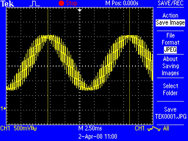
On the scope, it looks like the crystal is starting but it is sitting on a 75Hz sine wave. A capture of the wave form is attached. I've checked all of the power lines for noise and they are clean. I have changed the crystal out too.
Any ideas.... Anybody .... Anybody....
The chip programs via the Propellor tool and responds via the prop plug.
All of the I/O pins check out and run fine as long as I do not initialize the external crystal.
Any code that uses the:
_clkmode = xtal1 + pll16x
_xinfreq = 5_000_000
instructions locks up. As far as I can tell, it never executes a single instruction.
On the scope, it looks like the crystal is starting but it is sitting on a 75Hz sine wave. A capture of the wave form is attached. I've checked all of the power lines for noise and they are clean. I have changed the crystal out too.
Any ideas.... Anybody .... Anybody....
640 x 480 - 147K
Comments
▔▔▔▔▔▔▔▔▔▔▔▔▔▔▔▔▔▔▔▔▔▔▔▔
Paul Baker
Propeller Applications Engineer
Parallax, Inc.
Leon
▔▔▔▔▔▔▔▔▔▔▔▔▔▔▔▔▔▔▔▔▔▔▔▔
Amateur radio callsign: G1HSM
Suzuki SV1000S motorcycle
I have plans for several designs using the Propeller. I have seen problems like CannibalRobotics posted every now and again here on the forum. Is there something that can be done with external circuitry that helps to protects this failure from occuring? I assume it is occuring because of electro-static discharge or improper voltage.
▔▔▔▔▔▔▔▔▔▔▔▔▔▔▔▔▔▔▔▔▔▔▔▔
Timothy D. Swieter
www.brilldea.com·- check out the uOLED-IOC, an I/O expansion for the uOLED-96-PROP
www.tdswieter.com
One little spark of imagination is all it takes for an idea to explode
If you look at the data sheet the power supply pins only take a 3kV spike which is fairly easy to get. The i/o pins however will take more than 8kV which is a lot harder to generate.
If you could find a way of including some resistance on the power supply pins it would probably help.
If you are driving any coils, such as in a relay, be sure the coil has a reverse biased diode to sink the collapsing field and doing it on the transitor driver too doesn't hurt. Failure to do so will dump the charge onto the supply, into the Propeller and fry the PLL.
Ground loops occur when two points which are supposed to be an equal potential (such as the ground connections on two chips) are not the same potential. First, while it not directly related, all chips whose current consumption can rapidly change (such as anything containing·logic gates, ie all digital chips) should have a bypass capacitor, this helps to remove noise on the power supplies. Second the ground connections need to have as little resistance as possible, this means wide traces (This should be done for power too), and ideally the ground is a plane (and in 4+ layer designs power are planes as well). Take a look at the back of any Parallax product, see how the entire area is filled with copper? That is the ground plane, and it is there to minimize the potential for ground loops.
Also ALL propeller supply pins should be connected to the·other supply pins·at the Propeller (Vdd to Vdd, Vss to Vss), not doing this can cause a ground loop inside the Propeller. And never, ever use the Propeller's supply pins as a pass through (power supplied on one pin in turn supplies other components on another power pin not externally connected to the first pin, this is true for Vdd and Vss). You will be creating a ground loop if you do this.
Also in situations where multiple boards are connected together the common ground connection should be as hefty as practical. There's also issues with seperate AC powered boards, they should get thier power from the same outlet if possible (since ground loops can happen through your house/office's electrical system as well).
Lastly there is a phenomena with how current flows through the ground plane, it follows the path of the supply trace on the other side. Strange, but true. You should avoid breaking the path it wants to follow with any traces since it has to go around it, or at least minimize the distance it has to detour.
We follow these design rules and thus far have never had a design where the PLL failed.
▔▔▔▔▔▔▔▔▔▔▔▔▔▔▔▔▔▔▔▔▔▔▔▔
Paul Baker
Propeller Applications Engineer
Parallax, Inc.
Post Edited (Paul Baker (Parallax)) : 4/3/2008 2:03:22 AM GMT
Again, thank you for clarifying and elaborating on what could be done to design a more robust system.
▔▔▔▔▔▔▔▔▔▔▔▔▔▔▔▔▔▔▔▔▔▔▔▔
Timothy D. Swieter
www.brilldea.com·- check out the uOLED-IOC, an I/O expansion for the uOLED-96-PROP
www.tdswieter.com
One little spark of imagination is all it takes for an idea to explode
▔▔▔▔▔▔▔▔▔▔▔▔▔▔▔▔▔▔▔▔▔▔▔▔
Paul Baker
Propeller Applications Engineer
Parallax, Inc.
Jim-
▔▔▔▔▔▔▔▔▔▔▔▔▔▔▔▔▔▔▔▔▔▔▔▔
Paul Baker
Propeller Applications Engineer
Parallax, Inc.
Jim-
This is exactly the same as with the Stamps and is described in several Stamp tutorials including the Industrial Control tutorial.
1) I use a 1N4001 50V 1A diode, but lots of others will do. The cathode (banded end) is attached to the positive supply voltage end of the coil. The anode (other end) is attached to the ground end of the coil (usually towards the I/O pin). I've also used a 1N914 diode or a 1N4148 diode for reed relay coils.
2) This is usually a 0.1uF 50V ceramic capacitor connected between the Vdd and Vss (positive supply and ground) pins of the chip physically close to the chip Vdd and Vss pins. With small (less complex) chips like discrete logic gates, you can often get away with one capacitor shared between two physically adjacent chips.
Although they draw low average power, CMOS devices draw rather large current spikes while switching, which adds a lot of AC to the power lines.
Hope this makes things a little less mysterious.
▔▔▔▔▔▔▔▔▔▔▔▔▔▔▔▔▔▔▔▔▔▔▔▔
The more I know, the more I know I don't know.· Is this what they call Wisdom?
Regardless, I've installed a new chip on the demo board and added a diode. Works great again.
Oh, and thanks again for all that helped with my problem.
The board design is pure DC driven by batteries. The only inductive load element anywhere near the system is a 6vdc power supply rail for 8 servos. I've got bypass caps on either end of that. It's physically situated near the prop but there is a ground plane separating the header and the chip. The ground plane on the bottom of the board extends roughly 1/4" inch around the outside of the prop.
Jim-
▔▔▔▔▔▔▔▔▔▔▔▔▔▔▔▔▔▔▔▔▔▔▔▔
Paul Baker
Propeller Applications Engineer
Parallax, Inc.
All IC's should have a 0.1uF bypass on the supply line.
Circuit behavior will also depend *a lot* on the board layout: you typically don't put parasitics on the schematic, but they are there!
Posting reasonable pictures of the board's top/bottom would really help in assessing what may be wrong.
Note that probing high-frequency/wideband noise requires proper techniques, which are unfortunately relatively unknown to a lot of people [noparse]:([/noparse] To get a glimpse of what may be involved, read Linear Technology's app note AN70 - A Monolithic Switching Regulator with 100mV Output Noise. That appnote is lengthy for a good reason.
Silence is the perfectest herald of joy -- Shakespeare
The following code causes the LED to flash at about 2hz. I think the crystal is running around 5hz instead of 5mhz!
CON
_CLKMODE = XTAL1 + PLL4X
_XINFREQ = 5_000_000
PUB Toggle
dira[noparse][[/noparse]16]~~
repeat
!outa[noparse][[/noparse]16]