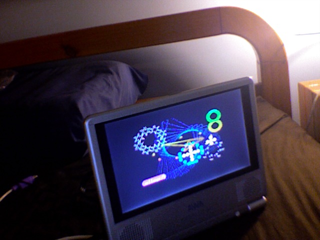
New screen
Well I just got a 7in monitor from Big W for $49 Aus
Seems to work alright. NTSC comes out as B&W but the colour works on PAL.
Now I will be able to test stuff without having to wait for the TV
And for the required pic. Sorry its not great but its inside with bad light from the camera in my laptop.
Seems to work alright. NTSC comes out as B&W but the colour works on PAL.
Now I will be able to test stuff without having to wait for the TV

And for the required pic. Sorry its not great but its inside with bad light from the camera in my laptop.


Comments
▔▔▔▔▔▔▔▔▔▔▔▔▔▔▔▔▔▔▔▔▔▔▔▔
http://www.propgfx.co.uk/forum/·home of the PropGFX Lite
·
▔▔▔▔▔▔▔▔▔▔▔▔▔▔▔▔▔▔▔▔▔▔▔▔
http://www.propgfx.co.uk/forum/·home of the PropGFX Lite
·
sorry, thought it was PAL & NTSC display [noparse]:D[/noparse]
▔▔▔▔▔▔▔▔▔▔▔▔▔▔▔▔▔▔▔▔▔▔▔▔
http://www.propgfx.co.uk/forum/·home of the PropGFX Lite
·
▔▔▔▔▔▔▔▔▔▔▔▔▔▔▔▔▔▔▔▔▔▔▔▔
http://www.propgfx.co.uk/forum/·home of the PropGFX Lite
·
I did a quick hack of the graphics demo to turn the prop into a TV clock, looks great.
From now on I will make sure that I have TV output option from my boards and not just VGA. Another connector perhaps lthough it is possible I guess to borrow some of those vga lines and feed a TV option out. It probably won't hurt to feed composite video out on pin 9 of the VGA connector which is normally a key pin.
*Peter*
I wonder if it is possible to figure out a system where either VGA or TV can be used from the same pin group. Maybe just a couple of groups of the resistors and some dip switches?
I'm in Brisbane. There should be no problem in paralleling resistors for the TV with the VGA signals directly from the Propeller I/O which is what I am changing on my designs.
If I want TV output then I simply use pin 9 of the VGA connector and set the Propeller to generate TV rather than VGA signals of course. I might even get rid of the bulky VGA connectors and just go RJ-45 with an external adapter lead, it simplifies case metalwork.
*Peter*
Take the case of VGA generation, the only difference is that the P16,P17,P18 are also connected to other resistors, but there is nothing in that setup that can affect the VGA signal. The resistors would have to be really low values and the I/O pins would have to be really weak outputs for there to be a problem.
Conversely, in the case of TV generation there is nothing that the VGA resistors can do to affect the TV signal. So just imagine that the I/O pins are low resistance switches to VDD or GND which effectively they are and you will see that this is so.
Of course in this circuit I would add the extra resistor to P19 for the sound anyway, whether it's used or not.
*Peter*