

Synth.spin square wave generation question
 automaton
Posts: 12
automaton
Posts: 12
Hello,
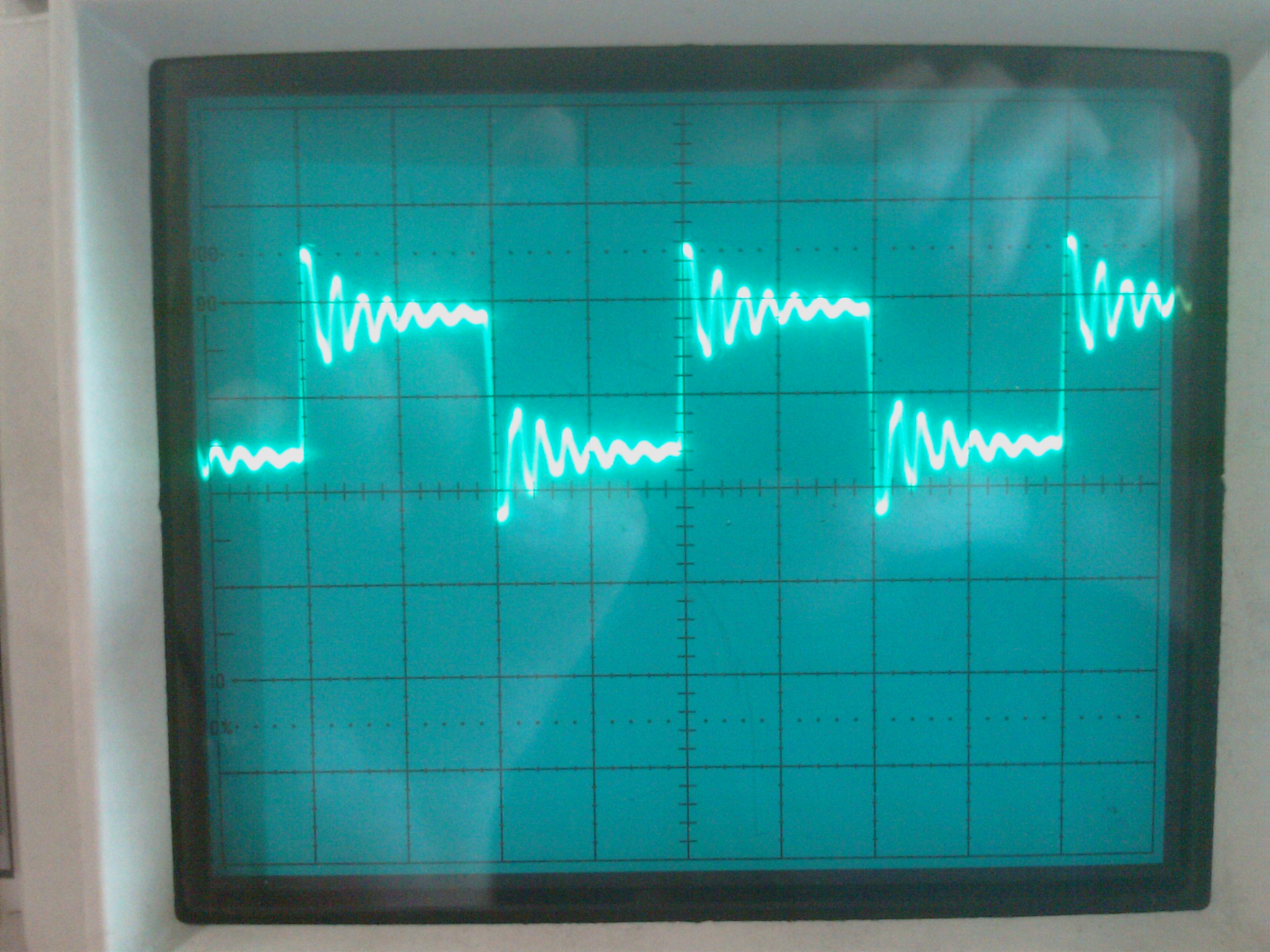
I·need to generate a high megahertz freqeuency·square wave·(between 1 and 10 mHz... all within that range)with a 3.3 volts peak to peak.· So i busted out the synth.spin, but to my dismay it was only putting·out around .5 volts peak to peak.· Its also a bit jittery.· Is there a reason for this?·
I suppose I could always use a seperate oscillator or crystal to generate a clean·square wave within my desired voltage ragne, but I've never directly worked with a crystal before, any suggestions on how to go about creating a square wave with 3.3 Volts between 1 mhz and 10 mhz?·
I was hoping for a MCU to do the job so that I could modulate the outpout frequency to any given value within my range.·
I've attached a picture of the square wave generated by synth.spin (imag0081.jpg.· Can anyone give me a suggestion on why the propeller is doing this or any alternatives?
Thanks
Post Edited (automaton) : 3/31/2008 8:54:30 PM GMT
2048 x 1536 - 578K
Comments
PLLs work on powers of two, frequencies other than a power of two ends up spliting the difference. This is jitter, and all PLLs exhibit it to varying degrees and the higher the frequency compared to the base frequency the more it's apparent. You will need to turn to more traditional methods of function generation if you need to have low jitter signals.
▔▔▔▔▔▔▔▔▔▔▔▔▔▔▔▔▔▔▔▔▔▔▔▔
Paul Baker
Propeller Applications Engineer
Parallax, Inc.
Post Edited (Paul Baker (Parallax)) : 4/1/2008 2:54:52 AM GMT
are there square waves or triangle waves being produced. I need 30Mhz square waves from the prop. I don't want to use a dss chip I would like to use the prop for all my projects if I can...
With my scope I got good square waves up to 10Mhz but it started to look like a saw tooth wave past the 10Mhz. Thanks
You should be getting much more than 0.5V and as Paul suggested, you are getting a lot of ringing which could be typical of inductive traces. The low voltage could be a sign of a bad ground connection even ground loops.· Make sure that your scope is connected on the same AC power as your PC,·Propeller board, etc.. and also make sure that the proper AC polarity and grounding is observed between the Propeller and your scope.
datacps,
"With my scope I got good square waves up to 10Mhz but it started to look like a saw tooth wave past the 10Mhz." - This may depend on the capabilities of the scope, and not the output of the Propeller. I have a 100MHz scope and I see similar characteristics at about 50MHz. However the same program running in Chips office on his high end scope, and the edges are perfectly clean.
▔▔▔▔▔▔▔▔▔▔▔▔▔▔▔▔▔▔▔▔▔▔▔▔
Beau Schwabe
IC Layout Engineer
Parallax, Inc.
Yup, I'm positive its is .2 V/div. To verify that its reporting the correct voltage, I ran the probes and the Oscope against its calibration· pins at that same volt/div and it correlates.· So·I'm getting that .5volts from visual inspection of that first spike (analog scope), but the majority of the information is below that.·
Anyways, as for the setup: Propstick USB, frequency is 2.5 mhz (or 5 mhz, I'm using both for experimentation purposes),·5 ~ 9 V (I've tried multiple voltage levels), standard breadboard, and a 465 Tektronix Oscope (an oldie but goodie).
The Oscope and the DC power generator are on the same ground, the generator is pumping in that voltage on pins 9 for Gnd and 12 for Vdd, I am also sending the frequency out of Pin 3.· There is no load on the propstick regulator.
To verify that the voltage I'm getting off of the Oscope is correct, on a whim I also hooked up a multimeter (at those frequencies, I'm assuming the multimeter should read a constant value since its sample rate is so low in comparison)... and it also reports the same mV value where· the majority of hte signal information lies... so thats some sort of comparison and validation of the Oscope.·
Just to play around with it I thought I'd hook it up to a 1K resitor, and it seems to have cleaned the signal quite drastically and has removed the ringing from the signal. Currently, with the·ringing fixed... I suppose I could send the square wave through an opamp go get the voltage range I need and be done with it, but i'd really like to know why the voltage isn't very high.· At least its stable in the sense that it is·repeating constantly and not fluctuating wildly from peak to peak.· But I'm not all that confident that the ringing is permanently fixed.
So I've attached the smoothed square wave and a picture of the setup.· Any help on what I'm doing wrong here or what I can do to fix it would be of help.· Thanks.
I'm just curious.... "...I am also sending the frequency out of Pin 3" , but the '94' image shows the resistor connected to P2.· Are you counting Pin0 as a valid pin number?
When I send a signal on P3 and connect a scope to P2, I see about a 160mV Pk-Pk signal at the correct frequency due to pin coupling effects.
What happens if you simply just make the Pin an Output and High? … or switch to a different pin?·· …What does the voltage read then?
▔▔▔▔▔▔▔▔▔▔▔▔▔▔▔▔▔▔▔▔▔▔▔▔
Beau Schwabe
IC Layout Engineer
Parallax, Inc.
Do get ~200mV on P6 though.· So, I'd guess you're on the wrong pin too.
Off by one on the low pin numbers, then progressively off by more and more towards the end.
Maintaining accuracy is a constant task.
▔▔▔▔▔▔▔▔▔▔▔▔▔▔▔▔▔▔▔▔▔▔▔▔
Harley Shanko
I also have another·spare propstick I can plug in and·see if its just a damaged propstick, something I didn't try yet.···
But the ringing effect is still present.. I can clean that one up pretty easily though.
Thanks for catching my mistake.. Doh!
Glad that you got it working... lol
▔▔▔▔▔▔▔▔▔▔▔▔▔▔▔▔▔▔▔▔▔▔▔▔
Beau Schwabe
IC Layout Engineer
Parallax, Inc.