

firing a npn problem.
 Jayguy5000
Posts: 139
Jayguy5000
Posts: 139
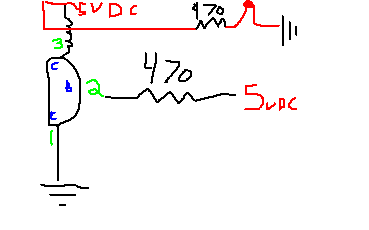
I have a npn transistor I am trying to get wired back up to work correctly. It USED to work with this schematic but Now I am having problems getting it work. The LED Is in correctly and working. I tested that small portion of the circuit. When I say I tested that portion of the circuit I mean I took the wire that connects the collector to the one end of the coil and took it out of the collector and straight to ground. That put 5vdc across the coil and 5vdc through the relay and the LED lit up! after I connect that wire back to the collector I get nothing. My goal is to get this to make the ground connection on a larger relay. The Resistors I am using are yellow violet brown. As you can see The collector goes across the coil of the larger relay connecting ground to 5VDC and making the larger relay work! Like I said this used to work great and now it doesn't..I Hope I have said everything you need to know to answer this question! If not ask away.
▔▔▔▔▔▔▔▔▔▔▔▔▔▔▔▔▔▔▔▔▔▔▔▔
Actually I think Im going to add the whiskers to my tank and let it roam, just need to figure out where.
Post Edited (Jayguy5000) : 3/30/2008 11:50:54 PM GMT
▔▔▔▔▔▔▔▔▔▔▔▔▔▔▔▔▔▔▔▔▔▔▔▔
Actually I think Im going to add the whiskers to my tank and let it roam, just need to figure out where.
Post Edited (Jayguy5000) : 3/30/2008 11:50:54 PM GMT
bmp
996K
Comments
It would be helpful to know the gain (hFE) of the transistor and the "pull in" current and resistance of the relay coil.
Post Edited (Mike Green) : 3/31/2008 12:02:54 AM GMT
▔▔▔▔▔▔▔▔▔▔▔▔▔▔▔▔▔▔▔▔▔▔▔▔
Actually I think Im going to add the whiskers to my tank and let it roam, just need to figure out where.
You do not have/show a free-wheeling (protection) diode across the relay.· That makes me think that your transistor is kaput.
See attached drawing.
There's a couple of pages in the "Industrial Design" tutorial from Parallax's Stamps in Class Downloads page that cover this. It's around page 90. Have a look.
However the attached will work better.
The 1N4001 diode across the relay coil helps to stop interference and damage to the transistor when the transistor turns off. Without it the transistor may no longer work!
the base resistor would be better at 4700ohm ie 4K7 yellow violet red.
The BS2 is unlikely to be able to supply or sink enough current to turn on the relay.
A 2N5961 has a maximum collector current of 50mA, most relays take more than this so you have probably blown the transistor.
A 2N5961 has a minimum gain of 150 so the gain isn't a problem, the current capability is.
Go buy a transistor with at least 200mA max collector current which should be enough but check the coil current of the relay.
David
▔▔▔▔▔▔▔▔▔▔▔▔▔▔▔▔▔▔▔▔▔▔▔▔
Actually I think Im going to add the whiskers to my tank and let it roam, just need to figure out where.
Post Edited (Jayguy5000) : 3/31/2008 12:36:10 AM GMT
A 1N4001 is good, a 1N400-anything will work.
Post Edit -- I believe that "we" were working with you on this about this time last year.
▔▔▔▔▔▔▔▔▔▔▔▔▔▔▔▔▔▔▔▔▔▔▔▔
Actually I think Im going to add the whiskers to my tank and let it roam, just need to figure out where.
The diode is a 1N4001 (1 amp diode) as it says on the diagram, I use them all the time, you could use a 1N914 or a 1N4148 diode or similar instead, just make sure it has the band at the 5v end otherwise it will fry and stop working. It normally doesn't conduct, but when the transistor turns off, the decaying magnetic field in the relay coil creates a reverse high voltage in the coil. One end is connected to 5v and the other end connected to the transistor can go several hundred volts positive, ie above 5v. The 2N5961 is only rated for 60v and the higher voltage will destroy it. The diode shorts out this high voltage to 5v so the collector of the transistor never gets more than 1 diode drop, about 0.7v, above the 5v line.
David
And the sort of small current low gain transistors needing 10mA base current haven't been around since manufacturers rejects were sold in hobby stores over 30 years ago.
These days low current (less than 1amp) transistors don't have gains of less than 100 (ok there may be one, but don't use it) and most have minimum gains of ~300 to 1000, with the average gain of a type being about twice the minimum.
To find out the base resistor required is very simple.
Take the 2N5961 as an example (Data from Towers International Transistor Selector)
If the maximum collector current for the transistor is 50mA
and the minimum gain is 150
then then the maximum base current required to fully turn it on is 50mA/150 = 1/3 mA =333uA
If the base resistor is connected to 5V either by a switch or the Stamp then the voltage across the base resistor
will be 5V-Vbe , ie about 5v-0.7v (for a silicon transistor), ie about 4.3V.
4.3V at 333uA equates to 4.3V/(1/3)uA = 4.3*3 Kohm = 12.9 Kohm
So using a 4K7 base resistor will allow just over twice the required current to saturate the transistor, which covers resistor tolerances, and less than 5V being delivered from an output pin etc.
So what is wrong with putting more current into the base?
It ends up as heat and damages/destroys the transistor that is what.
Try connecting the base directly to 5V while holding the transistor, it may get hot but it will die.
Using a 470ohm base resistor will give about 20 times as much current as needed!
A 1N4001 diode is rates at 1amp, try putting 20amp through it and see what happens, it will probably go FzzzzCRAcK and fall apart.
So go ahead, destroy your transistors if you want, but don't blame me.
David
▔▔▔▔▔▔▔▔▔▔▔▔▔▔▔▔▔▔▔▔▔▔▔▔
Actually I think Im going to add the whiskers to my tank and let it roam, just need to figure out where.
▔▔▔▔▔▔▔▔▔▔▔▔▔▔▔▔▔▔▔▔▔▔▔▔
Actually I think Im going to add the whiskers to my tank and let it roam, just need to figure out where.
If you connect the free end of the 4700 Ohm resistor to ground, the transistor will be off. If you connect the free end to +5V, the transistor will turn on. If you can't get it to work, then you've not wired it according to the diagram or the transistor is bad (unlikely).
Post Edited (Mike Green) : 3/31/2008 3:17:08 PM GMT
▔▔▔▔▔▔▔▔▔▔▔▔▔▔▔▔▔▔▔▔▔▔▔▔
Actually I think Im going to add the whiskers to my tank and let it roam, just need to figure out where.
Post Edited (Jayguy5000) : 3/31/2008 3:36:16 PM GMT
Just want to emphasize that it's not my circuit, it's Parallax's, and I agree with it.
Use an LED in series with a 1K resistor in place of the relay coil.
Do everything one step at a time and double check everything, including the continuity of your breadboard.
If you do it according to the circuits we have given you it will work.
David
If the LED is troublesome then try a small flashlight bulb since polarity doesn't matter so much.
Good Luck,
Robert
▔▔▔▔▔▔▔▔▔▔▔▔▔▔▔▔▔▔▔▔▔▔▔▔
Actually I think Im going to add the whiskers to my tank and let it roam, just need to figure out where.
I would be willing to bet you have the Emitter and Base reversed. Don't forget, there are several pinouts for the 2N2222. Some are E-B-C and some are B-E-C and maybe B-C-E. So double check your pinout for that particular device from the manufactures spec sheet.
▔▔▔▔▔▔▔▔▔▔▔▔▔▔▔▔▔▔▔▔▔▔▔▔
D. A. Wreski
I’ve never seen multiple pin-outs for the 2N2222, however I have seen many datasheets that show the pin layout from the bottom view, which I think confuses some people.
▔▔▔▔▔▔▔▔▔▔▔▔▔▔▔▔▔▔▔▔▔▔▔▔
Chris Savage
Parallax Tech Support
▔▔▔▔▔▔▔▔▔▔▔▔▔▔▔▔▔▔▔▔▔▔▔▔
Actually I think Im going to add the whiskers to my tank and let it roam, just need to figure out where.
Using a trusty (I can remember the pinout) BC109 npn
emitter to 0v
220R in series with a red LED from 5v to collector
with a 4k7 base resistor to 5v
the LED lights. (as it should)
Swapping emitter and collector (ie plugging in the BC109 backwards) makes no apparent difference to the LED brightness and the LED can be switched off as before by disconnecting the base from 5v.
Exactly the same with a BC549 (plastic BC109)
Doing the same with a 2N3906 pnp (emitter to 5v, LEd to 0v, base resistor to 0v), when plugged in backwards the LED is dimmer.
David