

bs2 / adc0838 / ka741 op-amp help
 paul1985
Posts: 8
paul1985
Posts: 8
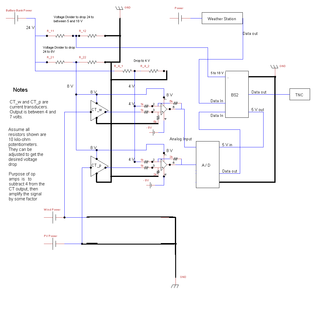
I'm having some trouble designing a circuit that will detect current using Hall Effect current transducers. The current from two different cables will be measured. The two transducers output a voltage between 4 and 7 volts (DC). I'm using an ADC0838 to convert these two signals to digital. I want the A/D to accept between 0-5 volts. The transducers do not output voltages within this range (they output between 4 and 7 VDC). Two KA741 op-amps are used to solve this problem. Each op-amp will subtract 4 voltage from the CT signal, then amplify the signal by a factor to increase the resolution and take advantage of the 0-5V range.
Before I begin to describe my problem(s), let us first make some assumptions:
- The ADC0838 has to accept a 0-5 V signal for my circuit.
- The op-amps are configured properly, i.e. they will subtract 4V from the input signal, and amplify it by the proper amount such that 0-5V can be output from the 741.
- All components are 'grounded' on a common float.
- My BS2 program works flawlessly as I want it to: Input A/D signal and another serial signal, output a serial signal.
- No power is given to the op-amps or current transducers. Power is only given to the BS2, which is to power the A/D. Therefore everything else is "off".
Here is my problem:
- We're drawing power from a 24 V battery (therefore DC). To power the BS2, a voltage divider is used to step the 24 V down to between 5.5 and 18. Two 10k-ohm potentiometers are used to do this. When I vary the unregulated voltage input between 5.5 and 18 (to pin 24), I should see no change in the 5 V output from pin 21. However, with my current circuit configuration, this voltage output changes as I change the input voltage between 5.5 and 18 VDC using the pots. I want the 5V to remain constant so it can power the A/D.
- I have a power supply handy in my lab, so I can simulate the 24 VDC. However, I can also simulate 5.5 to 18 VDC. When I bypass the voltage divider for the BS2 powering and input 5.5 to 18 V from my power supply in the lab, I get a consistent 5 V output from pin 21 on the bs2. When I apply 24 V to the voltage divider such that the output is between 5.5 and 18 VDC, the BS2 will NOT output a consistent 5 V. I've seen the BS2 output between 3 and as high as ~8 volts on pin 21 (I'm not 100% certain on this range, however it is a significant range that is nowhere close to my desired 5 V).
- I believe the problem may be caused by: 1) Ground looping, or something to do with everything being on a common float. 2) the op-amps 3) the voltage dividers
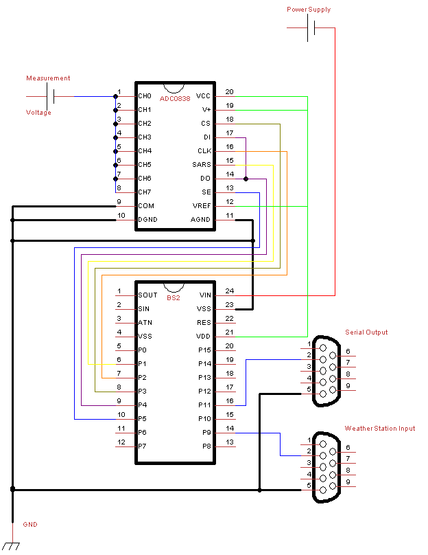
Attached is the schematic for my circuit, and then a schematic for the connections made between the BS2 and the ADC0838. I apologize for the sloppiness of the BS2-ADC schematic - it may be hard to follow. Also note that this is a hardware question, I'm assuming nothing is wrong with my BS2 programming, and I'm very confident that this is a correct assumption.
Thanks to anybody that is able to help. I don't have much experience with circuit design and/or electrical engineering. Any help would be appreciated!
Thanks,
Paul
Before I begin to describe my problem(s), let us first make some assumptions:
- The ADC0838 has to accept a 0-5 V signal for my circuit.
- The op-amps are configured properly, i.e. they will subtract 4V from the input signal, and amplify it by the proper amount such that 0-5V can be output from the 741.
- All components are 'grounded' on a common float.
- My BS2 program works flawlessly as I want it to: Input A/D signal and another serial signal, output a serial signal.
- No power is given to the op-amps or current transducers. Power is only given to the BS2, which is to power the A/D. Therefore everything else is "off".
Here is my problem:
- We're drawing power from a 24 V battery (therefore DC). To power the BS2, a voltage divider is used to step the 24 V down to between 5.5 and 18. Two 10k-ohm potentiometers are used to do this. When I vary the unregulated voltage input between 5.5 and 18 (to pin 24), I should see no change in the 5 V output from pin 21. However, with my current circuit configuration, this voltage output changes as I change the input voltage between 5.5 and 18 VDC using the pots. I want the 5V to remain constant so it can power the A/D.
- I have a power supply handy in my lab, so I can simulate the 24 VDC. However, I can also simulate 5.5 to 18 VDC. When I bypass the voltage divider for the BS2 powering and input 5.5 to 18 V from my power supply in the lab, I get a consistent 5 V output from pin 21 on the bs2. When I apply 24 V to the voltage divider such that the output is between 5.5 and 18 VDC, the BS2 will NOT output a consistent 5 V. I've seen the BS2 output between 3 and as high as ~8 volts on pin 21 (I'm not 100% certain on this range, however it is a significant range that is nowhere close to my desired 5 V).
- I believe the problem may be caused by: 1) Ground looping, or something to do with everything being on a common float. 2) the op-amps 3) the voltage dividers
Attached is the schematic for my circuit, and then a schematic for the connections made between the BS2 and the ADC0838. I apologize for the sloppiness of the BS2-ADC schematic - it may be hard to follow. Also note that this is a hardware question, I'm assuming nothing is wrong with my BS2 programming, and I'm very confident that this is a correct assumption.
Thanks to anybody that is able to help. I don't have much experience with circuit design and/or electrical engineering. Any help would be appreciated!
Thanks,
Paul
1094 x 1055 - 30K
624 x 808 - 14K
Comments