

1st soldered project having problems...
 Jed
Posts: 107
Jed
Posts: 107
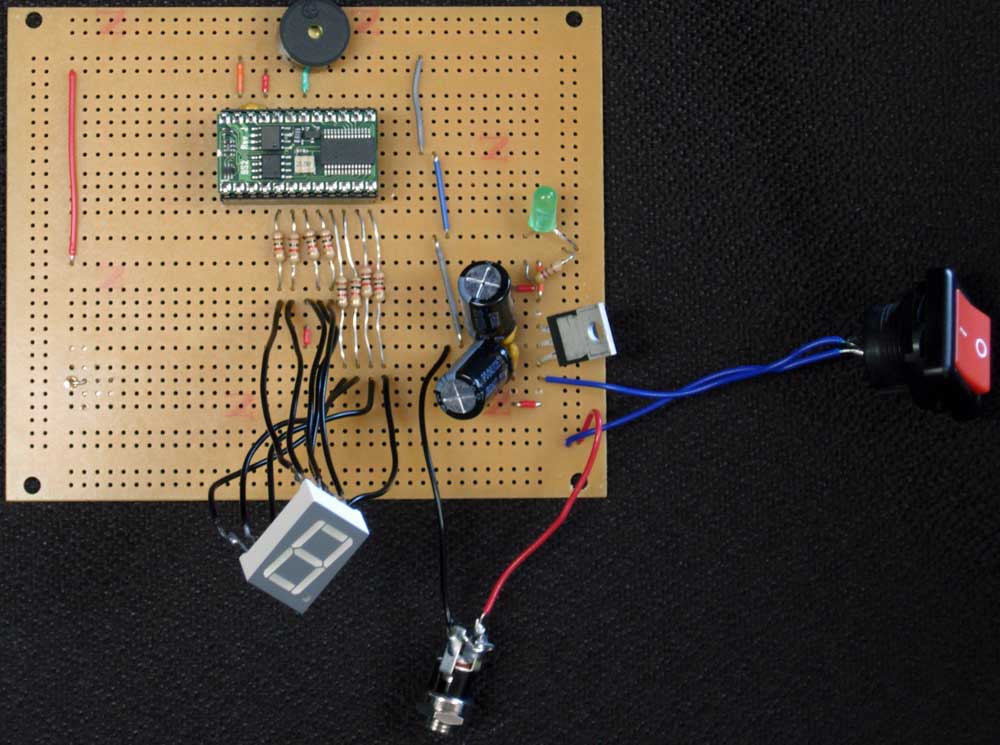
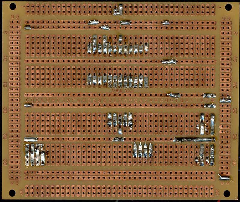
Ok, I'm soldering up my first prototype. I've got most of the connections made so I decided to test the board. I'm running a simple program as a test that will cycle through the 7-seg LEDs. The program works on the BOE, and I've also verified that the LEDs light if I manually connect wires from the BOE's output pins to my soldered project's LEDs, but for some reason when I pop the chip into the prototype nothing happens. I'm at a loss. I've attached a shot of the front of my board and the back as well as schematic. I mirrored the back to help see where connections are going. Does anyone have any idea why I'm having problems here? I know the back of the board is a bit messy (1st attempt at soldering), but I've verified through a magnifying loupe that there are no shorts on the backside. (there are some areas on the photo that look like shorts but it's just the wires sticking out on a diagonal angle).
Also, one other thing I've noticed: On my power connection. If I have the power switch set to off, then plug the power in, then unplug the power and then turn the power switch on, the power's LED lights up for a few seconds. Does the type of power switch I'm using have a cap or something built into it?
Post Edited (Jed) : 3/20/2008 1:24:49 AM GMT

Comments
2) If your program works on a BOE, then it should work on the prototype if that is wired correctly. You really have to start with your schematic and trace through everything all over again. Perhaps you can get someone else to look at it for you (the pictures are not adequate for this) while you go through the schematic and call out the expected connections.
I turn the switch off, THEN plug the power in, remove the power, THEN turn the switch on and I get a momentary current.
I/O Pins 9, 10, 11, 13, 14, & 15 are not wired yet (I wanted to test it first once I got the LEDs in there)
the reset pin is not wired yet. (normally floats if I'm not mistaken)
Those should not cause this problem though should they?
I'm going to go through with a multimeter and check for shorts tonight. Visually I can't see anything wrong with the way it's wired, but maybe I've got a bad solder joint or something. Power is getting to the power LED which is placed on the regulated side of power so I know that's not my problem. Is the cap between Vcc and vss on the stamp ok?
Post Edited (Jed) : 3/20/2008 1:26:40 AM GMT
Start with the PS, verify; then wire the power to the Stamp, verify; then add the LED circuitry, verify.