Shop OBEX P1 Docs P2 Docs Learn Events
Voltage Regulator and Capacitors — Parallax Forums

Voltage Regulator and Capacitors

Twisted PairTwisted Pair Posts: 177
edited 2008-03-16 10:24 in General Discussion
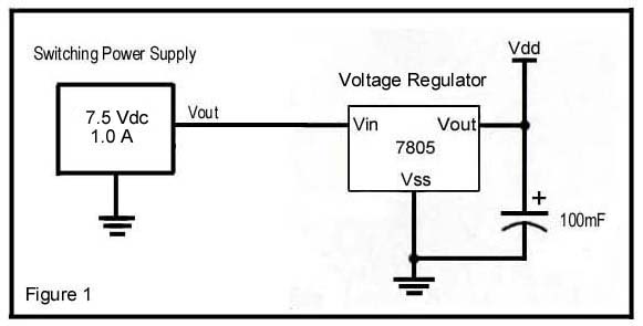
Hello everyone, I have a question regarding what the capacitor's on the input and output side's of the voltage regulator do. I have looked over the regulators data sheet and still haven't come to any kind of conclusion other than for stabilization·of certain kind of regulator circuits. I have attached a schematic of my power supply and regulator circuit. I'm using this circuit now in my project and it has been working without any flaws for many months.·My supply/regulator circuit is powering a BS2P24 that's running basically four Led's. Is my power supply and regulator circuit ok to run this way ?

Thank you for your help....

Twisted Pair....
581 x 295 - 16K

Comments

  • Mike GreenMike Green Posts: 23,101
    edited 2008-03-12 00:48
    The capacitor on the input side supplies current for a brief period when there's a sudden drain and the regulator is some distance from its power source (and maybe there's a lot of inductance in the wiring).

    The capacitor on the output side serves two purposes: 1) It supplies current at the regulated voltage when there's a sudden demand from the logic circuit while the regulator attempts to compensate. 2) It may be required for proper regulator operation. The datasheet for the regulator will indicate the minimum capacitance required.

    In general, follow the manufacturer's recommendations. In most cases, you want several hundred microFarads on the output side in parallel with a 0.1uF to 1uF capacitor on both input and output sides of the regulator.· If your circuit does not have large current spikes, you can go with the minimum output capacitor size recommended by the manufacturer.
  • Twisted PairTwisted Pair Posts: 177
    edited 2008-03-12 01:10
    Thank you Mike....


    Twisted Pair....
  • LeonLeon Posts: 7,620
    edited 2008-03-15 14:57
    The capacitor on the output also prevents the chip oscillating. A friend of mine didn't bother to include one once when he copied a power supply of mine, and then wondered why it didn't give any output. Just putting my finger on the output got it working, and adding the capacitor fixed the problem. You should have a 100nF capacitor close to the pins, as recommended in the data sheet. I generally use both the recommended 330nF on the input and the 100nF on the output (monolithic ceramics).

    Leon


    ▔▔▔▔▔▔▔▔▔▔▔▔▔▔▔▔▔▔▔▔▔▔▔▔
    Amateur radio callsign: G1HSM
    Suzuki SV1000S motorcycle

    Post Edited (Leon) : 3/15/2008 3:03:49 PM GMT
  • UghaUgha Posts: 543
    edited 2008-03-15 15:18
    This is a complete newbie question that I SHOULD know the answer to by now...

    Would it hurt anything to greatly exceed the recommended ratings?

    For example, if a 1uF is called for, would it be alright to use a 1000uF?
  • Mike GreenMike Green Posts: 23,101
    edited 2008-03-15 15:27
    Usually not a problem, although there are some exceptions:

    1) Some few specific models of regulators have limits on the size of the capacitor. Always check the datasheet.

    2) With very large capacitors, the surge current (to initially charge them) is pretty high and might cause the
    regulator to shut down briefly. We're talking here probably about well over 1000uF values.

    3) Sometimes the large value electrolytics have enough inductance or resistance that their RC or LC time is
    too high for regulator stability. You probably need a small (like 0.1uF or 1uF) capacitor in parallel with the
    larger capacitor and very close to the regulator.
  • UghaUgha Posts: 543
    edited 2008-03-15 18:06
    Great info as usual Mike.

    Now that you've listed the disadvantages of just using a 1000uF cap... are there any advantages of exceeding the
    datasheet's min value by about that much?
  • Mike GreenMike Green Posts: 23,101
    edited 2008-03-15 18:21
    Think of the output capacitor as a reservoir. If your device draws a relatively steady amount of current, you only need a small reservoir to keep it supplied reliably and the minimum output capacitance will probably work out fine. If your device draws a widely varying amount of current with lots of LEDs switched on and off and small motors or relays that might suddenly draw several hundred mA of current, you have a problem since the regulator and its "upstream" power source (the unregulated supply and the regulator's input capacitor) may not be able to supply the needed current as quickly as needed. That's where the output capacitor comes in. It supplies the current until the regulator and the unregulated supply can "catch up". The more the peak demand and the slower and more limited the upstream supply, the larger the reservoir you need.
  • UghaUgha Posts: 543
    edited 2008-03-15 22:38
    That's amazing. I've been trying to figure this stuff out for weeks.

    Thanks Mike!
  • RDL2004RDL2004 Posts: 2,554
    edited 2008-03-16 10:24
    Linear and Switching Voltage Regulator Fundamentals

    ▔▔▔▔▔▔▔▔▔▔▔▔▔▔▔▔▔▔▔▔▔▔▔▔
    - Rick
  • Please can you tell me the relationship between frequency and a capacitor? And how to determine the frequency of a capacitor?
  • Beavis3215Beavis3215 Posts: 229
    edited 2016-12-26 22:43
    z(capacitive reactance in ohms, or another way to think of it is the resistance in a circuit caused by capacitance under a frequency) = 1/(2 *pi * f * c). The definition of a capacitor is two conductors separated by an insulator.The capacitor component is built this way specially for different engineering purposes. Think about this though, you have a circuit running at a very high frequency where two wires are close together but not touching. The two wires are the conductors and the insulation and air in between are the insulator (the definition of a capacitor). The above formula means that If the frequency is high, the capacitive reactance is low, and there can be a flow of electrons between the 2 wires that are not touching. This flow is usually not wanted, and things like this need to be considered when building circuits. Using this principal, one can make a high pass filter. There is also a similar relationship for inductors.(kind of the opposite). For our purposes, running a microcontroller, we want our DC voltage to be as clean as possible. There are all kinds of ripples on unfiltered power that can be seen on a oscilloscope. Capacitors and inductors are tools in our toolbox for solving these problems. This is not the only relationship between frequency and capacitance. The resonant frequency of an LC circuit is F = 1/(2 * pi * sqrt(L * c)). This is used commonly in radio for tuning. To tune into a carrier frequency F, a value of L and C can be chosen using the above formula.
Sign In or Register to comment.