

voltage dropping without stamp or stepper activated; can you look at my diagram?
 Blake
Posts: 74
Blake
Posts: 74
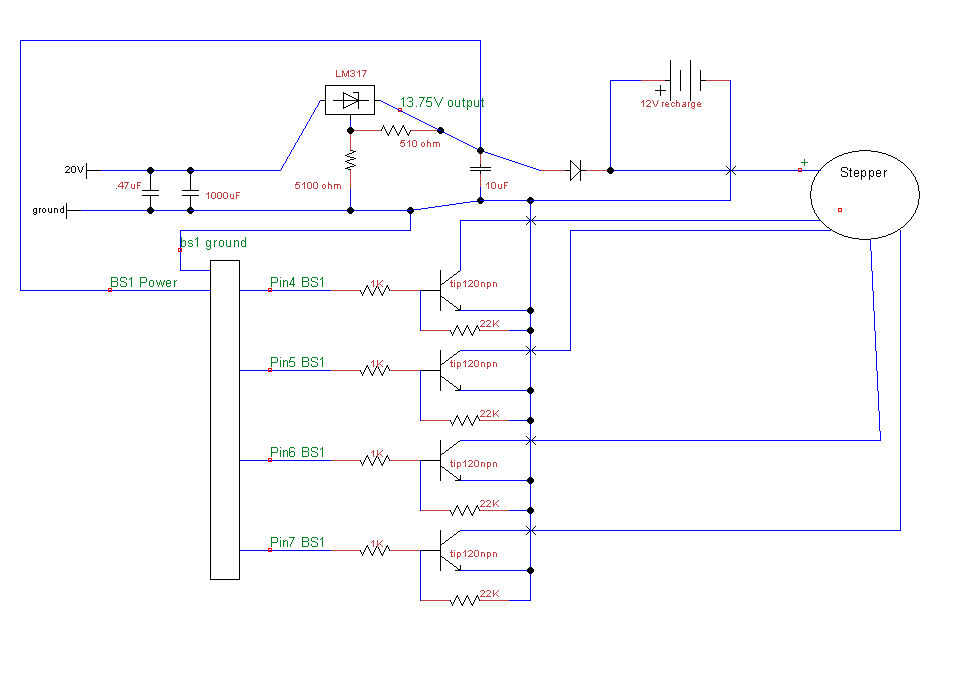
Hi, I have a quick question. Here's my diagram (from tinycad, first time):

(where the X's are, wires are not joining, just to be clear)
Without my basic stamp powered on (power and ground wires removed) and with the isolating diode, battery and stepper removed from the circuit (by pulling one leg of the diode out of my breadboard, i get 13.75Volts after the regulator with my multimeter. If i connect the diode to the circuit, without even connecting the basic stamp, i get around 8-9 volts measured in the same place. Does this indicate my base pins on the tip120's are letting a little current through even without the stamp active? Or what else could be taking away my voltage? I just don't get it.
Any help would be awesome. Also I know i need reverse diodes on the transistors, but they are not even active at this point. The voltage drops without triggering the bases or turning on the stepper, so i don't understand.
Thanks,
Blake
Post Edited (Blake) : 3/10/2008 2:51:05 PM GMT
968 x 677 - 11K
Comments
-Phil
Thanks,
Blake
Post Edited (Blake) : 3/10/2008 3:21:53 AM GMT
The 5100 Ohm and the 510 Ohm resistor form a voltage divider with your 20Volt input.... the largest amount that your regulator would see in this configuration is only about 1.82V
▔▔▔▔▔▔▔▔▔▔▔▔▔▔▔▔▔▔▔▔▔▔▔▔
Beau Schwabe
IC Layout Engineer
Parallax, Inc.
Post Edited (Blake) : 3/10/2008 2:51:43 PM GMT
With the TIP120's make sure that the 22K resistor is between the B-E junction, and not the B-C junction.
Also.... make sure that pin 1 (Base)·and pin 3 (Emitter) on the transistor are not swapped.
Curious... Is the stepper energized? i.e. is it difficult to turn in the condition that you describe?
▔▔▔▔▔▔▔▔▔▔▔▔▔▔▔▔▔▔▔▔▔▔▔▔
Beau Schwabe
IC Layout Engineer
Parallax, Inc.
Post Edited (Beau Schwabe (Parallax)) : 3/10/2008 6:34:15 PM GMT
Thanks,
Blake
http://www.blakefallconroy.com