

Twin Basic Stamp Protoboard
 Ugha
Posts: 543
Ugha
Posts: 543
I wanted you guys to take a look at something I've been working on the past couple days... it's
basically a protoboard meant for two BS2s (or any 24pin BS).
I've researched my butt off and duplicated a lot of different schematics combined in one...
plus added a lot of extra safeties that look like they may help (filtering caps, extra resistors
ect).
The basic concept is two BS2s on one protoboard (BOE-style) that can fully communicate and
share an on-board EEPROM. This will allow them to share stored data as well as access
condensed versions of programming (IE: Prescripted commands for robot movement, sound
emulation, whatever is needed repeatedly yet takes up tons of program memory).
It uses I2C for the communication with the EEPROM and a variation on the protocols found
in Nuts and Volts column #81.
The communication protocol will be simple... one BS2 will be the master, the other the slave.
When one stamp wants to use the EEPROM it will inform the other that its about to access the
EEPROM, thus locking it to the other stamp.
I'm concerned that I need to either put some larger resistors between the stamps and the
EEPROM or set the locked-out stamp to LOW or INPUT on the connected pins.
What do you guys think?
I'm not sure what EEPROM to use yet, I haven't got enough info yet to figure it out. Any
recommendations are welcome.
I picked the LM7805 voltage regulator instead of the one on the BOE because Peter Anderson
used it and the datasheet seems to show that its a bit tougher. I am slightly worried that
it will drain my batteries/heat up faster. (I don't fully understand voltage regulators).
I also want to eventually include programming on this board but I'm not quite sure how to go
about it yet (I don't understand how the connection works). I have an idea that I haven't
researched yet. Maybe one of you can enlighten me?
If I put a switch on the ATN line (A 2-position slide switch maybe?) to switch from one
stamp to the other and then ran SOUT and SIN to both stamps... would the "inactive" stamp
ignore the SOUT and SIN lines if there is nothing on the ATN line?
If this isn't very clear, let me know and I'll draw it out in detail.
I also had another idea... I read in a Nuts & Volts column that pins can be greatly protected
with a 1k resistor on it. I had considered including a 1k resistor on all pins on the board
but I was afraid it might mess up receiving analog signals. I'd like any opinion on this offered.
My final question is this: I had thought about making the master stamp able to reset the slave
using a transistor to tie it low then releasing it to float (this is what I can figure the
reset button does). Is this possible? And would it be possible to just run the reset pin
directly into an I/O pin on the master and have the master set the pin to LOW then INPUT?
My last question is... is there any harm in having components VERY close together? I want
to make this thing as small as possible (not much bigger than the three sockets together)
and I don't want to have any problems with noise caused by them being so close together.
This is part of the reason for all the 0.1uF filtering caps.
I know I'm dealing with concepts that a newbie of my knowledge level shouldn't be attempting,
and I know I'm most likely annoying you guys with my questions... but for some reason this
project just WON'T get out of my head. Its like an obsession or something.
I appreciate any input you can give me. Positive or otherwise.
Thanks goes out to
Peter H. Anderson
Jon Williams
Several Nuts & Volts columns.
Stampworks manual.
A ton of other sites and forum members.
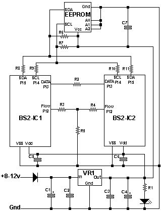
R1                  = 330 Ohm
R2                  = 1k Ohm
R3 & R4             = 470 Ohm
R5, R6 & R7         = 10k Ohm
R8, R9, R10 & R11   = 220 Ohm
C1                  = 220uF/25v
C2, C3, C5, C6 & C7 = 0.1uF
C4                  = 100uF/16v
VR1                 = LM7805
BS2-IC1 & BS2-IC2   = Any 24 pin Basic Stamp
EEPROM              = ?
319 x 420 - 33K
Comments
You need to understand the basics of electricity and electronics ... like become fluid with using Ohms law.
Understand the tradeoffs with using different kinds of voltage regulators. Understand what filter capacitors
are used for and how to choose their values. Understand how I2C works and how to use EEPROMs before
you try to share them between two master controllers. Experiment with networking and communicating
between two Stamps. If you don't understand the basics of switching a programming port between two
Stamps, you'll burn out stuff through ignorance rather than through carelessness or "bad luck". Adding a
1K resistor may prevent one kind of error, but introduce another. I'm not talking about becoming expert
in this stuff, just having a basic knowledge from starting simply using known good circuits and working
the tutorials and examples that Parallax already has.
That said, your diagram looks basically ok. I don't see anything that will get damaged.
Post Edited (Mike Green) : 3/2/2008 8:52:26 PM GMT
I live on a farm in the middle of nowhere. I have no access to a radioshack or any electronics
store (I checked, closest radioshack is 180 miles away).
I have no education in electronics or physics and no option to get one.
I have an extremely fixed income as far as hobby expenses (Basically whatever I can sell
my spare crops and eggs for has to be split among my family for luxury items). So I can't
even buy books to learn from.
Because of the bad weather, I've spent the past three weeks, around 16 hours a day,
reading every bit of info on basic electronics, the Basic Stamp and anything else related
I can find on the net. I've even read hundreds of forum posts from years back.
This is my only source of knowledge on electronics.
I understand that I don't know enough yet. That's why I post questions on this forum.
I had assumed that it wouldn't be a problem if I tried to learn as I went by seeking
the help from the experts here.
If I'm wrong in this, and if my posts are annoying or inappropriate, then please tell
me and I'll go elsewhere.
I apologize for exceeding my bounds.
It's kind of hard to expand them on $15 a month and a grade school education.
Perhaps you are not aware of the Parallax Education Program. Take a look at the link shown, for more information than you'll probably be able to consume in a year:
http://www.parallax.com/Default.aspx?tabid=362
Best of all, this course material is all FREE, and FREE is GOOD!
If you have a problem with a particular text, or experiment, please do us the favor of mentioning the following:
The title of the educational text you are reading
The experiment number (if applicable) in the text
The page number in the text
and finally
The question or problem which is puzzling you
That should give you the best chance of obtaining an appropriate answer from someone here on the Stamp Forums. Many have come before you, and used this method, and many will come after you as well. I hear nothing but success stories from those who've learned by these methods. I hope you will have that same degree of success.
Thanks go to Parallax for presenting an outstanding Education Program from which all can benefit. Thanks too to those who wrote the course materials, and manuals used in these education programs.
Regards,
Bruce Bates
▔▔▔▔▔▔▔▔▔▔▔▔▔▔▔▔▔▔▔▔▔▔▔▔
Programming can't be all that difficult, it's nothing but 1's and 0's
I can't complete most of the projects in the books because they require components I don't have, so I
just try to visualize it best I can.
In addition to that, I've read the stampworks documentation, the BS2 manual and a good 1/3rd of the
Nuts & Bolts articles. (talk about poor organization on topics... the titles are rarely related to the
subjects and there's no way to search them... but a DANGED good source of info).
I'm dedicated to learning this. I just don't have many resources at hand.
As far as what I might have problems with... I am confused about EEPROM somewhat (I mentioned my
lack of knowledge in the original post) and multiplexing as well as bit-shifters. But I haven't gone into
them too deeply yet.
I send you a PM
▔▔▔▔▔▔▔▔▔▔▔▔▔▔▔▔▔▔▔▔▔▔▔▔
··Thanks for any·
·
·
·
·
Sam
You are not exceeding any bounds in asking the questions that you have or in wanting what you seem to want. What I get from your posts is that you are very limited in the resources available, maybe other than the internet itself, and very hungry to learn. What you may be hearing from me (and maybe from others as well) is that there seems to be an order to what you have to learn. If you jump too far too fast, you will miss things that you'll need to understand along the way. Sure, you can get something built and it works, but you don't really understand what you're doing and, either you'll make mistakes that you don't see or can't figure out or you'll be too dependent on the knowledge of others to do what you want. Also, book learning only goes so far. You have to put the damn things together and see that they don't quite work the way the books say they should ... just like everything else in the world. If you haven't figured it out yet, the Wikipedia is your friend. The basic information is quite good and free and there's more than enough depth to get lost in.
The twin stamp idea is good - I'm working on a project now that has two stamps working in an integrated system. However, I think you need to make a few modifications to the design to allow for the program structure of the stamp.
Each processor should have its own eeprom to hold its program code, since in a master/slave relationship the master will be running different code than the slave. Likewise, only one should be accessing a data storage device, like a second eeprom on the master.
You want to avoid the situation known as a "deadly embrace". This is where each device is waiting to access a common resource and they each think it is currently "owned" by the other device. Since microprocessors typically do not have interrupt processing, which is what allows your PC to multitask and dual processor computers to keep track·of·which is doing what,·they can't easily resolve a "deadly embrace".
Dedicate resources to each of the processors and make sure the two processors can communicate (a simple dedicated serial circuit will work nicely for this). Then when you write code, the master has the code to direct an action to the slave and can continue on.
Just my 2 cents worth.
Thank you for your info and opinion. I appreciate it.
Everything you said makes absolute sense, but part of the reason for the design was so both stamps could share a central
EEPROM. This would allow them to access information without requesting it from the other stamp.
What I had thought was to use a Mutex (Stands for Mutual Exclusion, a term from multi-threading code, mainly related to
Windows programming).
Basicly each stamp would have a bit variable, whenever one stamp needs to use the eeprom, it would send a "mutex on"
signal to the other stamp. When the stamp is finished using the eeprom, it'll send a "mutex off" signal. Whenever this
variable is set to 1 (mutex on) then the Stamp either waits for it to be free or it'll continue with some other task and
try again later. This'll prevent simultaneous use.
If I write poor code that doesn't free the resource (EEPROM) for the other stamp when its finished, yes, we'll lock up
the program. But since this isn't an application where there will be other coders working on the design, I don't see it
as a problem... unless I get lazy (which has been known to happen).
However, if you think this can't work (I'm worried that I'll use up all the stamp's programming space just working out
the data handling and resource management and leave no room for it to actually DO something!), please by all
means let me know. I posted here cause I wanted to hear stuff exactly like what you said.
As far as a dedicated serial circuit for communication... I used a varation of what was in Nuts & Volts simply because
I'm not that educated about serial communication. I'd appreciate more info.
Although what you said did give me an idea... can I use the two serial pins for the two stamps to communicate or are
they exclusive to programming? (I can't find any info on using them so I'm assuming the latter).
Basiclly the concept is to take two stamps and make them parallel process tasks and problems. I know its not what they
are designed for, but they seem very flexible and quite capable of being adapted to the situation.
Mike Green:
I apologize if I misunderstood what you said before as discouraging.
I know there is a general order to the knowledge, and I'm finding that I'm very limited due to not following that order.
The problem is, I'm not sure what that order is.
In another day or so, I'll have read all of the Stamps In Class books (excluding toddler and sumo) and yet I am still
left lacking on some very important facts.
Everything I can find on the net is either:
A: Assuming you know nothing about electronics and tries to explain what the components are (What is a resistor, ect).
B: Assuming you already know the basics and gets too complicated to understand.
Most of my time is spent in various Wikis looking up terms that I found in OTHER wikis.
Its very hard to find any info on the next step of learning... to me that's how circuits work. How the various parts work
together in order to produce a useful result and more importantly... WHEN to use circuit A vs circuit B, or WHEN to use
component A or component B.
If I'm incorrect, if this is not the next step after learning what the components are and how they work, please let me know.
I very much would be relieved if I could find some ordered structure to learning this stuff that doesn't cost a fortune.
Example of what I've said:
The Stamps in Class books talk about using various ICs... temp sensors, digital pots, ect. But they never tell HOW they work
and WHEN you'd use them, all they say is how to wire them up and how to write code for them.
I know they are meant to be used in a classroom where students can ask the teacher, but its still very frustrating to someone
learning on their own.
of why you'd choose one part over another. Sometimes the various trade journals will have an article on certain types of design and why
a particular manufacturer's part or scheme is better than some others' and why. Magazines like Circuit Cellar and Nuts and Volts often will
mention this sort of thing in an article describing a construction project.
In the end, you will have to build things to learn. You will need some instruments. A simple multimeter is a necessity. I've seen good ones for as little as $10 mail-order on the internet.
It does help to have a project in mind, something that will be useful. For example, I have a dehumidifier with a tank that has to be emptied periodically. I have an aquarium pump that can empty the tank, but will eventually self-destruct if it runs dry too much. I need a timed switch that someday might be modified to test for the water level. I have to build a power switch, probably with a solid state relay and use a Stamp for a timer. Later I can tap into the existing switch that's used to turn off the dehumidifier if the tank is full, probably with an optoisolator. Now I have to get datasheets on optoisolators and solid state relays to figure out which one will work with the setup I have.
Post Edited (Mike Green) : 3/4/2008 1:49:16 AM GMT