

BS2 Homework/Motor Mind B hookup
 grottofilms
Posts: 6
grottofilms
Posts: 6
Hi all,
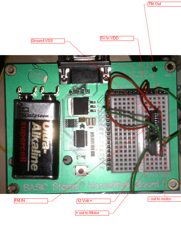
I'm a newbie to the basic stamp and I'm trying to learn about DC motor control using a Basic Stamp 2 Homeowrk Board and the Motor Mind B.· Can you look at my hookup and suggest why·the motor doesn't function?
The board is communicating with the motor mind:
STOP
SETDC
REV
TACH VALUE· = $00$00
SPDCON MODE
DONE
comes up in debug under the test program, but I get no motion.·
I've reviewed the literature, and everything seems right as I understand it.· My motor doesn't have a Tachometer...does that matter?
The green light flashes, indicating communication.·
The red light flashed once while I was testing, and I'm not sure if I need to clear the status somehow.· How exactly do I do that, anyway?
I've grounded the motor voltage to both the 9 volt terminal on the board and the VSS and the motor, but that doesn't seem to help.· The motor functions without the board.
Thanks for any help!
Best,
chris
631 x 864 - 363K
Comments
Along with what you've provided so far, a copy of the program (attached) would be helpful in troubleshooting the problem. Better than the picture you've provided would be a simple sketch or schematic of how you have the MMB wired to the breadboard.
Regards,
Bruce Bates
▔▔▔▔▔▔▔▔▔▔▔▔▔▔▔▔▔▔▔▔▔▔▔▔
"Genius is one percent inspiration and ninety-nine percent perspiration."
Thomas Alva Edison
' {$STAMP BS2}
'This routine steps through the entire command set available to users
'of the Motor Mind B.· The routine will loop through itself roughly
'every 75 seconds.· The confirmation byte and DEBUG routine are used
'to signal the user that a new command has been sent to and received
'by the Motor Mind B.
'
OUTPUT· 14
INPUT· 15
'
TM· CON· 15
FM· CON· 14
HIGH· FM
'
START_UP:
'Get out of SPDCON mode
· STATUS:FREQHI
· LOW·· FM
· PAUSE· 300
· HIGH· FM
· PAUSE· 25
· PAUSE· 1000
'
'Send STOP command
'
· SEROUT· FM,396,[noparse][[/noparse]$55,$80]
· SERIN· TM,396,100,NO_CONFIRM1,[noparse][[/noparse]B7]
· IF B7 = $AA THEN CONFIRM1
CONFIRM1:
· DEBUG· "STOP",CR
NO_CONFIRM1
· PAUSE· 3000
'
'Send SETDC command, set duty cycle to 'DD'h, or 86.2%,(Dec 221 out of 256 possible)
'
· SEROUT· FM,396,[noparse][[/noparse]$55,$83,$DD]
· SERIN· TM,396,100,NO_CONFIRM2,[noparse][[/noparse]B7]
· IF B7 = $AA THEN CONFIRM2
CONFIRM2:
· DEBUG·· "SETDC",CR
NO_CONFIRM2
· PAUSE· 3000
'
'Send REV command
'
· SEROUT· FM,396,[noparse][[/noparse]$55,$81]
· SERIN· TM,396,100,NO_CONFIRM3,[noparse][[/noparse]B7]
· IF B7 = $AA THEN CONFIRM3
CONFIRM3:
· DEBUG· "REV",CR
NO_CONFIRM3
· PAUSE· 3000
'
'Send TACH command and read back/display tachometer frequency
'
· SEROUT· FM,396,[noparse][[/noparse]$55,$82]
· SERIN· TM,396,500,NO_CONFIRM4,[noparse][[/noparse]B7,B8, B9]
· IF B7 = $AA THEN CONFIRM4
CONFIRM4:
· DEBUG·· "TACH VALUE· = "
· DEBUG·· ISHEX2· B8
· DEBUG·· ISHEX2· B9,CR
NO_CONFIRM4
· PAUSE· 3000
'
'Send SPDCON command, freq. set to 100Hz('0064'h)maintain for 60s
'
· SEROUT· FM,396,[noparse][[/noparse]$55,$84,$00,$64]
· SERIN· TM,396,100,NO_CONFIRM5,[noparse][[/noparse]B7]
· IF B7 = $AA THEN CONFIRM5
CONFIRM5:
· DEBUG·· "SPDCON MODE",CR
NO_CONFIRM5
· PAUSE· 60000
'
'Return to normal operating mode
'
· DEBUG· "DONE",CR
· GOTO· START_UP
END:
Here's the best schematic I could make; I'm just an novice at this point.
Thanks for any help or thoughts!
Have you checked the voltage at Motor + and Motor - to ensure that you have the voltage you expect to see there (12 VDC)? If not, check the 12 VDC source to make sure it is supplying voltage to the MMB.
Your schematic may just be a bit incomplete, but where you have noted the GND terminal of the MMB going to Vss, does that also go to the ground side of your 12 VDC power source? If not, that is probably your answer. Here is the reason I mention that.
It's unclear from what you said above:
"I've grounded the motor voltage to both the 9 volt terminal on the board and the VSS and the motor, but that doesn't seem to help."
as to whether VSS is tied back to the (-) terminal of the 12 VDC power source or not.
Let us know how you make out.
Regards,
Bruce Bates
▔▔▔▔▔▔▔▔▔▔▔▔▔▔▔▔▔▔▔▔▔▔▔▔
"Genius is one percent inspiration and ninety-nine percent perspiration."
Thomas Alva Edison
Thanks so much for your help!
there's no voltage coming from the Motor Mind, I checked with my multimeter. I get voltage out of the battery, it's not dead. I'm getting a solid reading on the other side of the same row where the 12v+ goes in, directly behind the MMB.
I'm not sure what you mean by tied back, but I've connected the grounds from VSS and -12V Battery and together they feed into the MMB ground. Still not voltage for motor + and motor-.
Thanks again!
Chris
Do you have any reason to think the MMB was damaged at some time?
There are no fuses in your MMB wiring configuration, are there?
Regards,
Bruce Bates
▔▔▔▔▔▔▔▔▔▔▔▔▔▔▔▔▔▔▔▔▔▔▔▔
"Genius is one percent inspiration and ninety-nine percent perspiration."
Thomas Alva Edison
Thanks!
Chris
What kind of 12 volt battery are you using to power the motor?
Regards,
Bruce Bates
▔▔▔▔▔▔▔▔▔▔▔▔▔▔▔▔▔▔▔▔▔▔▔▔
"Genius is one percent inspiration and ninety-nine percent perspiration."
Thomas Alva Edison
Just out of sheer curiosity, where did the following come from, in terms of which exact manual had the coding which contained it:
STATUS:FREQHI
That oddity can be found in the START_UP routine, even in the coding provided in your prior post . I've looked at 3-4 program examples, which contain code exactly like that above, but WITHOUT that unusual sequence in it.
Regards,
Bruce Bates
▔▔▔▔▔▔▔▔▔▔▔▔▔▔▔▔▔▔▔▔▔▔▔▔
"Genius is one percent inspiration and ninety-nine percent perspiration."
Thomas Alva Edison
Best,
chris
has this problem been resolved?