

awesome console plan
 dfletch
Posts: 165
dfletch
Posts: 165
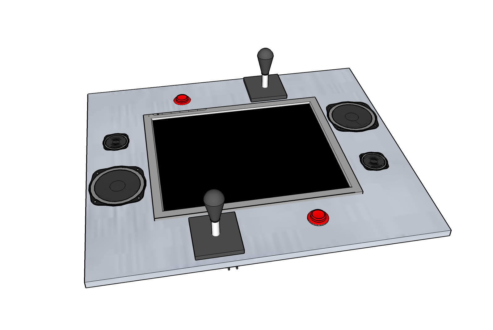
I'm a bit proud of this and just had to share. This is going to be so cool!
Using the joysticks in 8-way configuration with an SD card for the sound and VGA output this will use all 32 pins!
The modeling software I did this with is really neat! sketchup.google.com/ It has this great feature where it uses google.com to find and import models directly. The Happ joystick and pushbuttons I planned on using were in there! There's decent models in a search for "LCD" and "speaker" too.
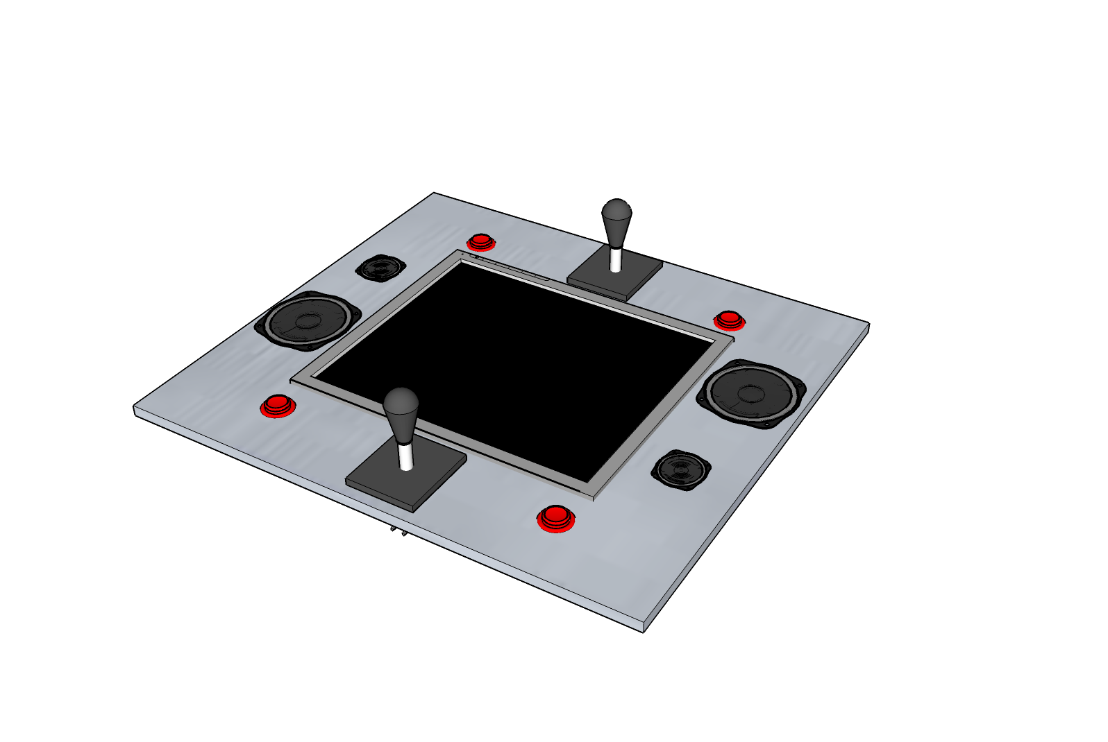
UPDATE: Took QuattroRS4's advice and made it friendly for lefties too!
▔▔▔▔▔▔▔▔▔▔▔▔▔▔▔▔▔▔▔▔▔▔▔▔
Join us in the Un-Official Propeller IRC channel: irc.freenode.net #propeller
Newbies, oldies, programmers, math professors, and everyone in-between welcome!
Propeller IRC howto
spinc - open source Spin compiler
Post Edited (dfletch) : 3/25/2008 7:06:07 AM GMT
Using the joysticks in 8-way configuration with an SD card for the sound and VGA output this will use all 32 pins!
The modeling software I did this with is really neat! sketchup.google.com/ It has this great feature where it uses google.com to find and import models directly. The Happ joystick and pushbuttons I planned on using were in there! There's decent models in a search for "LCD" and "speaker" too.
UPDATE: Took QuattroRS4's advice and made it friendly for lefties too!
▔▔▔▔▔▔▔▔▔▔▔▔▔▔▔▔▔▔▔▔▔▔▔▔
Join us in the Un-Official Propeller IRC channel: irc.freenode.net #propeller
Newbies, oldies, programmers, math professors, and everyone in-between welcome!
Propeller IRC howto
spinc - open source Spin compiler
Post Edited (dfletch) : 3/25/2008 7:06:07 AM GMT
1596 x 1070 - 186K
1596 x 1070 - 166K
Comments
8 pins for each joystick = 16
1 pin for each button = 2
4 pins for SD card = 4
8 pins for VGA = 8
2 pins for speakers = 2
TOTAL 32 pins
But you still need 2 pins for the eeprom and 2 pins for the programmer.
You could save a lot of pins by using shift registers for your joysticks and buttons like on the Hybrid.
Nice layout though.
Looks like we are assuming all players are left handed !
Perhaps the Joysticks shoule be central ?
JT
▔▔▔▔▔▔▔▔▔▔▔▔▔▔▔▔▔▔▔▔▔▔▔▔
'Necessity is the mother of invention'
I believe I'll use my own VGA driver derived from my learning driver, and my own graphics/sprite lib. I'm not in any hurry, and want to make this excellent.
The opposing controls mean text / graphics in both directions. This whole thing is a fun challenge for me and a way to learn all about every aspect of the prop.
Cheers,
--fletch
If not I stand corrected in terms of gaming posture ! ..Looks well though ..nice idea..
John
▔▔▔▔▔▔▔▔▔▔▔▔▔▔▔▔▔▔▔▔▔▔▔▔
'Necessity is the mother of invention'
Good point John, Thanks!
@fletch: It is common to multiplex slow input devices as buttons or (digital) joysticks. And a 4-way jouystick should have 4 relevant lines, not 8.
If you are not familiar wit multiplexing you should learn it - it is one of the 10 basic techniques needed to use microcontrollers with some proficiency
Though 74HC chips generally come down to 30 cents, I like the $2 PCA8574 best. It connects to Pins 30 and 31 and that's ist. Have a look at my "Small I2C Driver" I posted two or three months ago giving an example for it's usage.
Post Edited (deSilva) : 2/22/2008 9:45:10 AM GMT
Not a 'leftie' myself but was just looking at your image and it occurred to me ... keep us posted on progress..
Regards,
John
▔▔▔▔▔▔▔▔▔▔▔▔▔▔▔▔▔▔▔▔▔▔▔▔
'Necessity is the mother of invention'
(4) connected to 2 PCA8574's
(2) one each for each player's button (or I could go nuts and do up to 8 total buttons and one use one more PCA8574 here)
(8) VGA
(4) SD
(4) audio
22 pins, serious room to spare now!
What else could I hook up to it? I could put a ring of LEDs around the whole thing with all the pins I have left [noparse];)[/noparse]
That gives me an idea! I can pick up similar chips from my regular supplier but they're SO-16. Looks like I can fit 3 on a piece of schmartboard, which gives me lots of inputs on a nice standoff board.
you only need 1 pin for mono audio or 2 for stereo, no need to waste 4 pins on it [noparse]:)[/noparse]
MCP32017 ww1.microchip.com/downloads/en/DeviceDoc/21952b.pdf with already 16 I/Os in PDIP-28 or QFN
deSilva: yep it's just my supplier doesn't have any of the DIP packages. I could shop around, but I'm a bit lazy [noparse]:)[/noparse] Any idea where to order them in the US? (mouser is the one with only SO-x options).
would love to see the rest of the table or what ever it's going to be, don't for get cup holders!!!
▔▔▔▔▔▔▔▔▔▔▔▔▔▔▔▔▔▔▔▔▔▔▔▔
"A complex design is the sign of an inferior designer." - Jamie Hyneman, Myth Buster
DGSwaner
Dgswaner: Thanks, I'm glad you like it! This box though is going to be given away to someone, and will only play 1 game - it's a fancy "resume", and the game will be my life - building RC gadgets as a kid, learning programming as a young adult, development work as an adult. It will all be shown top-down style and be very 80's arcade, but the audio will be much better than that
If this all goes well, I'll build one for myself! That next rev will have (hopefully) 2 trackballs in addition to the joysticks, more buttons, and an external slot for the SD card for easy updating.
Cheers,
--fletch
Cheers,
--fletch
Using a counter is fine, but you will need the reset in any case, thus 2 lines at least. Of course you can control the counters by the PCF-chip! Just add the (pull-up) resistor (=10 k or such)
I'm still slightly confused about this output. So the pull up resistor turns it into a normal positive output?
Cheers,
--fletch
▔▔▔▔▔▔▔▔▔▔▔▔▔▔▔▔▔▔▔▔▔▔▔▔
Join us in the Un-Official Propeller IRC channel: irc.freenode.net #propeller
Newbies, oldies, programmers, math professors, and everyone in-between welcome!
Propeller IRC howto
For more clarity I enclose the circuitry from the datasheet.
A pin can be programmed as HIGH, which means
- EITHER ready for input, however as it is biased to HIGH it behaves a little bit like the OLD TTL inputs, so pull-ups are not needed in most cases....
- OR you use it for output but may only draw a very low current (100µA) out of it. That is quite different from standard CMOS outputs, but it suffices to drive a LS-TTL load or just keep the voltage up.
If the pin is programmed to LOW it will be low and can sink upto 25 mA.
As I see it now it does not even seem necessary to add an extrnal collector resistor even when using it as output, as long as you will not need more than 100µA, corresponding to a 33k resistor.
To give you an example:
An LED should be conected to PLUS 3V using a 150 Ohms resistor (PIN -- short end LED long end -- resistor -- PLUS)
This is sometimes called "negative logic", as setting it LOW it shines, and setting it HIGH it does not
You can never conect it to GND as you generally do!
However you can connect it as follows:
(PLUS -- 150 Ohms resistor (+) LED -- GND)
Then tap the point (+) between LED and resistor by the output pin
This is POSITIVE logic. The current for the LED comes straight out of the external "collector" resistor and does not load the chip! However when you switch off the LED this happens by short-circuiting the LED.. NOW all the current flows though the chip.
This is not a very advantagious situation, but many things are possible...
Sorry to have confused you, but is simpler than you now think. But I start to understand now why these chips tend to be less popular among hobbyists....
Post Edited (deSilva) : 2/23/2008 7:09:29 PM GMT
I've made the beginnings of the layout for the expander card (screenshot). All the expanded IO lines are there, just need i2c and power lines.
This is going to be so cool
I'll post pics of the steps as I built it.
Cheers,
--fletch
▔▔▔▔▔▔▔▔▔▔▔▔▔▔▔▔▔▔▔▔▔▔▔▔
Join us in the Un-Official Propeller IRC channel: irc.freenode.net #propeller
Newbies, oldies, programmers, math professors, and everyone in-between welcome!
Propeller IRC howto
spinc - open source Spin compiler