

Can you use ferrite inductors as electro-magnets?
 John Bond
Posts: 369
John Bond
Posts: 369
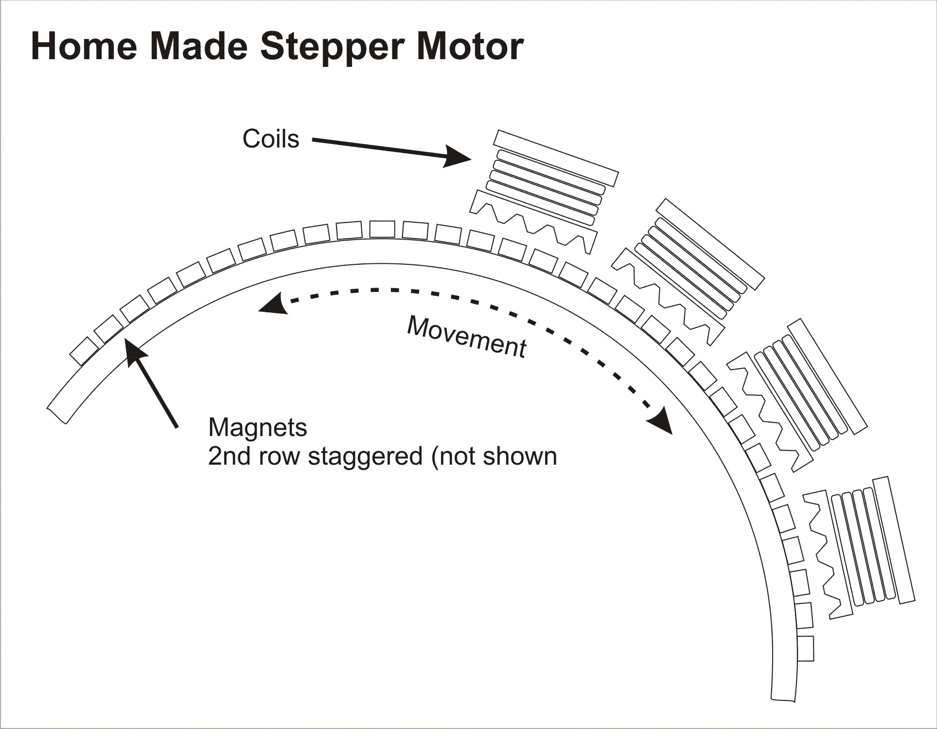
I’d like to try to build a “linear” stepper motor. The application doesn’t have space for a normal stepper or the gears and rack (or even space for a rod or band as used in old floppy drives). The motion is an arc.
·
Question:
Can I use Large Ferrite Inductors (pre-wound) “off the shelf” and machine the magnetic·teeth into their head?
Wikipedia on Stepper Motors
http://en.wikipedia.org/wiki/Stepper_motor
·
Thanks and kind regards from Darkest Africa.
·
·
John Bond
- Edited to change picture type
▔▔▔▔▔▔▔▔▔▔▔▔▔▔▔▔▔▔▔▔▔▔▔▔
Post Edited (John Bond) : 2/21/2008 7:27:14 AM GMT
·
Question:
Can I use Large Ferrite Inductors (pre-wound) “off the shelf” and machine the magnetic·teeth into their head?
Wikipedia on Stepper Motors
http://en.wikipedia.org/wiki/Stepper_motor
·
Thanks and kind regards from Darkest Africa.
·
·
John Bond
- Edited to change picture type
▔▔▔▔▔▔▔▔▔▔▔▔▔▔▔▔▔▔▔▔▔▔▔▔
Post Edited (John Bond) : 2/21/2008 7:27:14 AM GMT
1932 x 1503 - 271K
Comments
I suppose the obvious question, before you get to machining your own stepper motor, is how much space DO you have? There are plenty of miniature, sub-miniature, and micro stepper motors. One company that imediately comes to mind is MicroMo. Here is a link to their miniature stepper motors: http://www.micromo.com/n112508/n.html .
If that's not small enough, let me know, as I've seen even smaller ones available from a German company, whose name escapes me at this moment.
Regards,
Bruce Bates
▔▔▔▔▔▔▔▔▔▔▔▔▔▔▔▔▔▔▔▔▔▔▔▔
"Genius is one percent inspiration and ninety-nine percent perspiration."
Thomas Alva Edison
Thanks for the link. There is space for the slide... and nothing more. As I've said, I even looked at locating the stepper remotely and using an actuator rod but there's other machinery in the way.
No space to the left, no space to the right, a little space above (where I thought of putting the coils) and all the action takes place below so I can’t put anything there.
I’ve given this idea a substantial amount of thought over the last three years, including 3D CAD drawings and a Plastercene (clay) model. I’ve always concluded it can’t be done. I even thought of doing it pneumatically, making a curved cylinder, but there is no compressed air near by. When I looked at an article on a Rail Gun in the latest Nuts&Volts, I wondered if I couldn’t go the same way. Last night I stripped a couple of stepper motors and was pleasantly surprised. While two had soft iron cores, an old one had two rows of small magnets. They all had coils that looked a lot like big ferrite chokes. I wondered if I could do the same.
Kind regards
John
▔▔▔▔▔▔▔▔▔▔▔▔▔▔▔▔▔▔▔▔▔▔▔▔
I'm sure your design makes a good deal more sense to you then that rather simple picture, but here are a few questions I have:
1. How are you going to insure equal spacing of these coils across the arc space?
2. What is the point or purpose of the "magnetic teeth "? Is this some sort of gearing? If so, are you prepared to cut your own gears on a mill?
3. Linear steppers are certainly available, as you know. Have you checked to see if they are offered in an arc-type configuration?
4. If you don't mind my asking, what is the application?
More questions than answers, but sometimes that's how solutions magically appear
Regards,
Bruce Bates
▔▔▔▔▔▔▔▔▔▔▔▔▔▔▔▔▔▔▔▔▔▔▔▔
"Genius is one percent inspiration and ninety-nine percent perspiration."
Thomas Alva Edison
1. The sketch only indicates the coils and the magnets in relation to the slide. the slide is well mounted (aluminium running in hardened steel though I may have to replace the aluminium with mild steel to assist the magnetic field) There is no play. I haven’t worked out the mounting of the coils but as they are fixed (as against the moving magnets), this shouldn’t be too difficult.
2. The magnetic teeth in a conventional stepper motor increase the number of steps (indents) per revolution. This isn’t critical in my application and I may just leave them out.
3. I’ve done a search for arc linear stepper motors but I think that where one has an application such as this, you tend to use a normal stepper driving a rack and pinion. That’s how I’d do it if I could.
4. The application is part of the assembly of the wiring harness on Toyota IMV/Hilux trucks. Because of poor design, it’s difficult to assemble one of the connectors but, as Toyota practices “Global Manufacturing” and this harness is made in 5 other countries, we can’t get the design of the harness changed.
It's one of those areas where you always think "There has to be a better way".
Kind regards
John Bond
▔▔▔▔▔▔▔▔▔▔▔▔▔▔▔▔▔▔▔▔▔▔▔▔
I've pondered the use of ferrite beads, and they seem really unneeded - a design distraction.· Coils with mild steel cores might be helpful. I may be wrong, but I·think the ferrite beads are used to shift permability to higher frequencies for effiency and size reduction of transformers.· The issue is what is a good electromagnet rather than what is a good transformer.· Ferrite is monolithic, so physical layers don't vibrate against each other.
IN sum, I've never seen an electric motor with a ferrite component.
▔▔▔▔▔▔▔▔▔▔▔▔▔▔▔▔▔▔▔▔▔▔▔▔
PLEASE CONSIDER the following:
Do you want a quickly operational black box solution or the knowledge included therein?······
Post Edited (Kramer) : 2/21/2008 11:28:32 AM GMT
That's exactly what I want to do. Where do I get the coils, probably not more than 25mm high and anything up to 25mm wide. It would be better if they were oval because I could pack more coils. above the rail.
By the way, I was not thinking of ferrite beads but rather the large ferrite inductors (as in large chokes) though it could be coils from relays or any other pre-wound device with suitable core. I think there will be at least 16 of these coils and I don't want to make the cores and wind them myself. (8 coils per phase - bipolar)
John Bond
▔▔▔▔▔▔▔▔▔▔▔▔▔▔▔▔▔▔▔▔▔▔▔▔
As always, an interesting mind challenge. Can you fill us in on a couple of other points?
What is the total linear travel needed? What's the arc radius? Once started, does the system travel to the end or does it need to stop at some point midway?
Finally, how much force are you hoping to generate?
As for getting the coils, most small motor rewind shops can do this for you. They can make up a winding jig, use a piece of soft iron as a core and wind them on a lathe. They won't be zero-cost, but may give you enough pieces to get going.
Cheers,
▔▔▔▔▔▔▔▔▔▔▔▔▔▔▔▔▔▔▔▔▔▔▔▔
Tom Sisk
http://www.siskconsult.com
·
1. The diameter of the circle that forms the arc is +-80mm and the arc travels from mechanical stop 120mm to mechanical stop. It is either open or closed and should never need to stop anywhere else.
2. The minimum force needed is moderately high, approximately 0.5 KgF (5N or 1LbF). Probably twice as much if I take into account inefficiencies caused by future wear and dirt.
3. You have a point - I live a little distance from civilization so I usually opt to order by mail than travel the 100 mile round trip to my nearest motor rewinder. Also, motor rewinders in SA usually only do 220V motors so I've never tried their skills on a 12 or 24V armature. I don't even know if they have soft iron core material but I'll phone some in the morning to find out.
Thanks for your input
John Bond
▔▔▔▔▔▔▔▔▔▔▔▔▔▔▔▔▔▔▔▔▔▔▔▔
Have you considered using a push/pull cable?· This method is very commonly·used in aircraft to provide linear motion in very small spaces.· Many general avaition aircraft link cockpit controls to wing control surfaces this way and those forces can be quite high in some cases.· It sounds to me like this may fit and work in your application, and allow you to place whatever you want to dive it with, in a more spacious remote location.
Tim
Edit: Just to clairify... when I say that forces can be quite high, I'm talking about·tens of pounds easily.
Post Edited (Tim-M) : 2/21/2008 8:03:48 PM GMT
John,
The force that can be generated by your coil on a modified ferrite core depends
on several factors:
1) The number of ampere-turns in the coil
2) permeability of the ferrite core material
2) The Reluctance of the full magnetic circuit.
You can minimize the Reluctance by keeping the air gap as small as practical.
What will limit the ampere-turns is the B-H curve of the ferrite material
you're using. When it saturates, you can't get any higher flux thru the core.
You might want to see if the manufacturer of your particular ferrite
core has specs on saturation levels and permeability. If it isn't published
on the Internet, an email to him should get the data you need. He may
also have info regarding the application you're considering.
phil
http://www.danahermotion.com/website/usa/eng/products/motors/brushless_motors/brushless_direct_drive_linear_motors.php
These are probably far too pricey and complicated but the basic principle is there. I'll look around at the shop for some sketches with internal layouts on Monday, but its essentially a row of rare earth magnets that mount down solid and a 3 phase winding laid out flat.
Solarbotics is the only source of a 'pre-made' magnetic coil that I am aware of. You might be able to get blank 'bobbins' to wind your own, but I would have to go visit several local stores to see if they really have them.
You might find that you can salvage pre-wound bobbins from relays, but stay away from AC relays with a shaded pole unless you remove the core. The shade pole feature is there to eliminate vibration caused by the AC cycle.
Magnetics is a complex field. In many ways, it is more complex that other aspects of electronics becasuse there are many ways to create the same field density [noparse][[/noparse]a heck of a lot of variables to consider in 3 dimensions]. A trial and error approach may be fast if you are lucky or you might find weird behaviors.
Another place to locate prewound coils on bobbins is from the backside of 16, 8, or 4 ohm speakers. Obviously the resistances and power ratings are already known.
▔▔▔▔▔▔▔▔▔▔▔▔▔▔▔▔▔▔▔▔▔▔▔▔
PLEASE CONSIDER the following:
Do you want a quickly operational black box solution or the knowledge included therein?······
Thanks for your “in-depth” responses. I’ve learned lots about motors, stepper motors and electromagnets in the past 48 hours.
The repeated comment on using a wire or rod has made me do some thinking. I can’t use a rod because of all the surrounding stuff… but I could use a miniature timing belt with half a dozen idler pulleys to route it to a convenient spot.. I could then put the motor anywhere and just fasten the belt to either end of the slide. I’ll also have to make a tensioner because the length of belt would change as the slide moves.
This weekend I’m going to build a small “proof of concept” linear stepper motor using coils out of automotive relays and I’m also going to look at the use of a timing belt.
This problem has so excited me that today I woke before 04:00am, walked down to the old disused New Guelderland Station and sat on the platform thinking and watching the two early morning freight trains come rumbling through. What an amazing dawn, all pink and blue. I listened to the noisy Egyptian geese waking up on the nearby dam and greeting each other.
Thanks again for all your help and kind regards
John Bond
▔▔▔▔▔▔▔▔▔▔▔▔▔▔▔▔▔▔▔▔▔▔▔▔
Marty
▔▔▔▔▔▔▔▔▔▔▔▔▔▔▔▔▔▔▔▔▔▔▔▔
Lunch cures all problems! have you had lunch?
Thanks for the idea Marty. I'll look at them today.
I got a little 4 coil, 6 magnet linear motor to push the stator along, but without much force. The coils (broken up Automotive relays) used about 300ma.
On the other hand, our maintenance guys are well down the track using a long timing belt. Problem appears to be solved.
Thanks again
John Bond
▔▔▔▔▔▔▔▔▔▔▔▔▔▔▔▔▔▔▔▔▔▔▔▔
▔▔▔▔▔▔▔▔▔▔▔▔▔▔▔▔▔▔▔▔▔▔▔▔
Never give up,·Never submit to the seemingly invincible enemy.
This is drawn from memory. The maintenance guy jumped at the idea of using a belt and just went and did the job
Thanks for all the assistance
John bond
▔▔▔▔▔▔▔▔▔▔▔▔▔▔▔▔▔▔▔▔▔▔▔▔