

Paranoid newbie needs approval on circuit design
 Ugha
Posts: 543
Ugha
Posts: 543
Hello all,
I'm a complete newbie when it comes to electronics. My real
passion is programming... so I'm a bit paranoid when it comes
to things I come up with on my own.
I've got three boebot kits and a few other sources that I've
been ripping parts out of... and I've come up with my own
circuit.
But the problem is, I'm scared to death of the thing. I've
never before worked with capacitors or transistors other than
following directions in books like the boebot manual.
In fact, I'm still slightly confused on the applications of
capacitors other than the application I've put it to here.
Basicly, I'd like to know two things... if I hook this up to
my stamp, will it harm anything? I'd also like to know if its
possible to do this in a more simple manner.
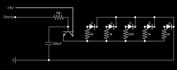
What I've designed is a circuit that causes a bank of five leds
to fade on and fade off. I'm aiming for a blinking/fading
"mouth" to a head (head being a robot that remains still
and interacts like a simple head and shoulders... like a very
simple form of kismat).
The outter leds should fade off before the center one. I was
unable to figure out how to do this, so I'm just faking it
by decreasing the voltage over the outter ones so they are
dimmer.
My original design simply put a capacitor in parallel with the
leds, this worked great for fading out, but required a very
large capacitor (470pico farad) and I still couldn't get the
outter ones to fade faster.
My second design uses a transistor and the smallest capacitor
I have. I'm not 100% sure what it is, I think its its 100nF.
It says 103 on it.
Basicly, if you guys would look at this and make sure it won't
fry my stamp, I'd very much appreciate it.
I'm a complete newbie when it comes to electronics. My real
passion is programming... so I'm a bit paranoid when it comes
to things I come up with on my own.
I've got three boebot kits and a few other sources that I've
been ripping parts out of... and I've come up with my own
circuit.
But the problem is, I'm scared to death of the thing. I've
never before worked with capacitors or transistors other than
following directions in books like the boebot manual.
In fact, I'm still slightly confused on the applications of
capacitors other than the application I've put it to here.
Basicly, I'd like to know two things... if I hook this up to
my stamp, will it harm anything? I'd also like to know if its
possible to do this in a more simple manner.
What I've designed is a circuit that causes a bank of five leds
to fade on and fade off. I'm aiming for a blinking/fading
"mouth" to a head (head being a robot that remains still
and interacts like a simple head and shoulders... like a very
simple form of kismat).
The outter leds should fade off before the center one. I was
unable to figure out how to do this, so I'm just faking it
by decreasing the voltage over the outter ones so they are
dimmer.
My original design simply put a capacitor in parallel with the
leds, this worked great for fading out, but required a very
large capacitor (470pico farad) and I still couldn't get the
outter ones to fade faster.
My second design uses a transistor and the smallest capacitor
I have. I'm not 100% sure what it is, I think its its 100nF.
It says 103 on it.
Basicly, if you guys would look at this and make sure it won't
fry my stamp, I'd very much appreciate it.
590 x 235 - 28K
Comments
▔▔▔▔▔▔▔▔▔▔▔▔▔▔▔▔▔▔▔▔▔▔▔▔
Chris Savage
Parallax Tech Support
Terry
A few questions...
Chris Savage: First, I only have one transistor in the schematic. Second... I really appreciate your advice and I will of
course follow it... but can you tell me why this is better? I can't learn if I don't understand the "why" as well as the "how".
Terry_bear: Any suggestions on how to rig up the second capacitor? Basicly copy the way I have it there (with Chris'
recommendations of course) and run it parallel to what I've got already? Or would that work? All of my attempts to
connect a second capacitor affects the entire circuit, which is why I haven't included one in the schematic.
I thought the 470 was an electrolytic... it came with the boebot kit. I thought electrolytics were the barrel-shaped ones
that are polarized. Shows how much I know [noparse]:)[/noparse]
As far as making it start dark than fade on... not in my experimentation. Could I have placed the resistor in the wrong
location or something?
Finally...
I still haven't got an answer to my most worrying problem... Can this circuit in any way (Or any one involving capacitors)
damage the BS2?
Thank you for your understanding... this newbie greatly appreciates it [noparse]:)[/noparse]
Beau Schwabe had a nice article about transistor biasing I think some time ago…Let me see if I can find it…
http://forums.parallax.com/attachment.php?attachmentid=37701
Okay, that wasn't exactly what I was thinking...I will look some more...But definitely read that link.·
▔▔▔▔▔▔▔▔▔▔▔▔▔▔▔▔▔▔▔▔▔▔▔▔
Chris Savage
Parallax Tech Support
It did tell me that there is a lot more to transistors than just NPN vs PNP though... thank you [noparse]:)[/noparse]
As far as redoing my circuit according to your instructions, I've attached a modified version that I
THINK is what you meant. I haven't tested it yet because I wanted to make sure I understood you
first.
Excuse the poor layout of the new circuit, I was more concerned with getting it right than appearance.
▔▔▔▔▔▔▔▔▔▔▔▔▔▔▔▔▔▔▔▔▔▔▔▔
Chris Savage
Parallax Tech Support
It doesn't work.
The leds don't fade on or fade off.
I'm wondering if I wired something wrong (although i've checked a dozen times) so I think I'll
post some pictures of the actual circuit.
Unfortunately, my camera isn't the best quality so the images are quite blurry.
I'll post two images, one as-is and one with numbered regions explaining what isn't quite visible.
A couple things first... I haven't hooked it up to the stamp yet, so I'm using a 9v battery for
the supply and a push-button to simulate the high/low commands.
The regions are:
1: The switch simulating the stamp's signal.
2: The 10k resistor going to the base of the transistor.
3: The capacitor going from the base of the transistor to ground.
4: The transistor.
5: The junction from the transistor's emitter and the capacitor that goes to ground.
6: The cathodes of the LEDs are all connected together in parallel.
7: The anodes are connected through the resistors in parallel.
I hope this makes some kind of sense... please let me know if you see why the circuit no longer works
with the redesigned layout.
Edit:
I forgot to make clear that the LEDs DO come on when you press the button, they just don't fade on or off.
I think you need to go with an "emitter follower".· See the attached schematic.
I think the capacitor is too small a value here, too.
Post Edit --
The base voltage will ramp up till C is charged and ramp down when the input voltage (stamp output)·is turned off.· The emitter voltage will "follow" the base voltage, it will be 0.7V less.
You'll have to experiment with values of C and R as well as·output Hi/Lo times.
Post Edited (PJ Allen) : 2/12/2008 2:07:43 AM GMT
Or am I missing something?
My comment about the fade being from off to on was about your original circuit (not the first one that you sent), where you stated that you had put the cap in parallel with the LEDs.
I think that P Js' emitter follower may solve the fade-on- fade-off problem, but it will still affect all the LEDs at the same time. Effectively, the cap only sees one resistor (composed of series and parallel sums of the various resistances in the circuit) and charges and discharges through that. Starting with your current schematic, I suspect that a separate transistor and base resistor would be needed (at the very least) for the second string of LEDs.
By the way, you are quite right about the barrel shaped caps being electrolytics. 470 pf caps are not normally polarized and not electrolytic.
As P J says, the cap value may still be too small, but that isn't likely to radically affect the operation. That will be a matter of fine tuning, as it were...
Terry
If you want a ramping voltage applied to your LEDs to vary their intensity, then emitter follower is the way to go.
Basicly PJ says go back to my previous schematic...
Terry says either go back to my previous schematic, or add a lot of components to get the current one working...
So the logical choice is to go back to the original... except...
Chris said that this new design is better... but never explained why.
I'm so confused.
You haven't tried yours/mine.· I think that it will be fine, nothing will be destroyed (if you follow the plot.)
Switch around a·few wires -- or don't.
Chris: If you have a chance sometime soon, can you go into more detail about why your design is better? I'd really
like to not only learn to make things work, but learn the proper protocols and practices to get them there, as well
as learning WHY they work.
Thank you all for your advice and help.
For what it's worth, I bread-boarded P Js' circuit with one LED, and it comes on quickly compared to how it goes off, but there is still fade-on. The fade-off is much longer. I'm using a 3300 micro-farad cap. If I get a chance and find the parts, I'll add a second LED and transistor to the pin that I'm driving it with...
Terry
I then went to a grounded emitter (like the first schematice that you posted, Ugha), but with the cap across the transistor. That seems to be working very well, although with a 1000 micro-farad cap it may be slower than you want... The timing can also be changed somewhat by changing the value of the collector resistor, but that will affect the brightness more, I'm afraid.
·
There is nothing wrong with either circuit....
Your original design, a Common-Collector configuration, is basically·a voltage buffer or current amplifier.· This circuit is useful because it has a large input impedance and a small output impedance.
·
The other circuit is known as a Common-Emitter configuration and is·often used·as a voltage/current amplifier.· It is probably the most popular configuration and most widely used.·
·
A third·configuration type not mentioned·is a Common-Base configuration.· It basically functions the opposite of a Common-Collector configuration in that it acts as a current buffer or voltage amplifier.· It exhibits a very low input impedance and a high output impedance.····
·
For your particular application, a current amplifier or Common-Collector configuration might be better suited for driving·LED's.
·
·
▔▔▔▔▔▔▔▔▔▔▔▔▔▔▔▔▔▔▔▔▔▔▔▔
Beau Schwabe
IC Layout Engineer
Parallax, Inc.
Question though... what are the benefits of a Common-Emitter? Why is it more popular than the other two?
I think that I may have inadvertently contributed to a lot of your confusion. Somehow I got the impression that you wanted fast on and fade to off, and I see from the original post that that wasn't the case...
So, the only real problem is getting two (or more) fade times, and that means two (or more) capacitors and transistors.
Terry
I'd just like the "fast" on to fade in instead of just blink on.
So super-fast fade on.. then slower fade off.
Allow me to explain a bit more what I wanted...
My intention is to use my 5 leds as a "mouth" display for my robot.
The BS2 will set one pin to high, pause a half-second or so, then set it
to low.
As soon as the pin is set to low, a tone will play as a method of "talking".
The tone will be based on the robot's current emotion and method of
stimuli.
I knew that the BS2 can only do one action at a time, so I figured a fade-off
will make the "mouth" appear to be still on when the tone actually sounds.
Each additional "word" spoken will relite the led bar to full brightness and
then cause it to fade again. This will give the impression of multiple syllable
words being spoken very quickly.
Hopefully this will happen so fast that the tones will appear to trigger at the
same time as the lights to the human eye.
Anyway... the fade-on aspect isn't needed. I just kind of thought it'd look
neat. In practice, the instant-on followed by fade-off works quite well.
The only thing I wish I could figure out is how to change the fade rate of
the different LEDs
Example:
All leds off:
|OOOOO|
A "word" is spoken...
|@@@@@|
|O@@@O|
|OO@OO|
|OOOOO|
But this isn't a requirement... as I've adjusted the resistors on the outter four pins
to create an illusion of this.
Anyways... I hope this clears things up.
P.S. - I have my digital camera today and may be able to get a short video clip of it working.
▔▔▔▔▔▔▔▔▔▔▔▔▔▔▔▔▔▔▔▔▔▔▔▔
Chris Savage
Parallax Tech Support
Post Edited (Chris Savage (Parallax)) : 2/12/2008 3:27:39 PM GMT
ftp://ftp.parallax.com/video/1K_1000uF.MPG
ftp://ftp.parallax.com/video/4K7_1000uF.MPG
ftp://ftp.parallax.com/video/10K_1000uF.MPG
The second way to drive the base is to bring it HIGH then OPEN.· A BASIC Stamp output pin could do this by setting the output HIGH then toggling the pin between INPUT and OUTPUT.· This is simulated in the following video using a 1K resistor for a fast rise time but slower decay time.
ftp://ftp.parallax.com/video/1K_1000uF_Open.MPG
I hope this provides some useful insight.· Take care!
▔▔▔▔▔▔▔▔▔▔▔▔▔▔▔▔▔▔▔▔▔▔▔▔
Chris Savage
Parallax Tech Support
·
·
What you originally have, a Common-Collector, also works as a current regulator, where a Common-Emitter configuration·will not.
·
A transistor operating in it's linear region is most sensitive near the Base-Emitter(B-E) threshold.· This threshold voltage is typically 0.6V
·
If the voltage across the B-E goes above 0.6V the transistor is "ON" and if it falls below 0.6V, the transistor is "OFF".· What's different with a Common-Collector configuration, that a Common-Emitter configuration does not have, is that when the transistor turns "ON" it biases the ground reference at the emitter by allowing voltage at the collector to conduct.· The result is that the B-E junction "sees" less than 0.6V and tries to turn off the transistor.· Since there is virtually no hysteresis, instead of turning the transistor "OFF", the voltage from the collector is "pinched" until there is an equilibrium in the circuit ...·this would be the ability to regulate the current.
▔▔▔▔▔▔▔▔▔▔▔▔▔▔▔▔▔▔▔▔▔▔▔▔
Beau Schwabe
IC Layout Engineer
Parallax, Inc.
Just interjecting a bit here. I think you are reading into it all too hard. It sounds like to me that if you want a robot's mouth to light up based on a spoken word recording, then if follows that the lighted mouth should react directly to the sound itself and not trigger the lights first and THEN the audio. It just wouldn't look realistic.
So this really sounds as simple to me as using an LED VU meter...except instead of one going from left to right (as on sound system), it is one that starts in the center and radiates outward. There are many IC's on the market that will do this very thing such as the LM3914. This driver IC supports 10 segments so you can double up on the LED outputs to have a mouth 20 segments wide! Realistically you could probably just take it to 5 segments out each side. You can also adjust the decay using a capacitor as well for that 'fade out' effect. It is a helluva lot simpler than dealing with separate components and all the current calculations. Besides if you still want a drive from a Basic Stamp, you can do so via a D/A conversion. In this manner you can control exactly how the mouth moves based on a control voltage in relation to the spoken word. But doing this will take up a chunk of operational functionality on the Basic Stamp. Functions which you can delegate to other parts of the robot...such as eye and head movement. Speaking of which, a great idea for an eye would be one of those scanning Cylon eyes...if you are into the cyclops look. I have worked on quite a few programs for the BS2 in regards to that application.
Bottom line...for voice think you are best to stick with the LM3914 for now.
I just hooked up the base to the piezo's pin.
The frequency might not be steady, but its hardly possible to notice it with the human eye... and it has
benefits:
The LED stays on throughout the entire sound, as if the robot was actually speaking and this was it's
"mouth-open" state.
With super-low frequencies (10-100 range) from the piezo, the leds dim slightly which I find creates
a very realisitic affect.
And the best benefit of all... it frees a pin.
Have fun,
Terry