

Twisted transistors! overamperage concern for BS2
 firestorm.v1
Posts: 94
firestorm.v1
Posts: 94
Ok, working with transistors again (yes this has something to do with my other post about serial ports)
I have come up with a simple design that I wanted to run by more educated and smarter people than myself to see if I have left anything out.
I know that the BS-2 can't source more than 20mA, is that a per-port limitation? Does going through the transistor alleviate this?
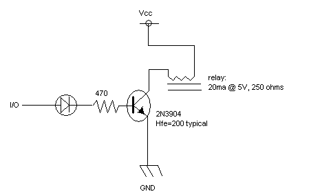
What I am thinking of doing is creating a relay-array that is software controlled by a host computer (hence the serial port post). In order to do that, I am wanting to make sure that with all 8 indicator LEDs fired up (imagine 8 copies of the schematic below) that the amperage requirement is not exceeded. according to my math each LED/470 ohm combo will use 7.23 mA. Assuming that is a per-port limit, then I should be able to build many of these without fear of destroying the I/O pins. (the regulator I'm not worried about as they Vcc for the transistor/relays will be fed off of a 5v, 1a regulator and I don't anticipate even with 16 relays of over-drawing the amperage on that.
Any insight would be helpful as I'm still trying to learn. [noparse]:)[/noparse]
I have come up with a simple design that I wanted to run by more educated and smarter people than myself to see if I have left anything out.
I know that the BS-2 can't source more than 20mA, is that a per-port limitation? Does going through the transistor alleviate this?
What I am thinking of doing is creating a relay-array that is software controlled by a host computer (hence the serial port post). In order to do that, I am wanting to make sure that with all 8 indicator LEDs fired up (imagine 8 copies of the schematic below) that the amperage requirement is not exceeded. according to my math each LED/470 ohm combo will use 7.23 mA. Assuming that is a per-port limit, then I should be able to build many of these without fear of destroying the I/O pins. (the regulator I'm not worried about as they Vcc for the transistor/relays will be fed off of a 5v, 1a regulator and I don't anticipate even with 16 relays of over-drawing the amperage on that.
Any insight would be helpful as I'm still trying to learn. [noparse]:)[/noparse]
bmp
17K
Comments
The diode needs to be across the relay to dissipate the reverse EMF when the transistor shuts off. It needs to be a power diode (typically 50V at 1A) and is connected in reverse with the cathode to the positive supply. You don't need a diode coming from the I/O pin.
You could easily use a 1K resistor in the base lead which would cut the per pin current in half, then put the LED and a separate current limiting resistor in parallel with the relay coil. You can choose whatever resistor value you want for brightness.
Post Edited (Mike Green) : 2/10/2008 11:22:11 PM GMT
The LED was more for status indication than anything, but using that resistor will ensure I don't pull too much amperage from the BS2.
To make sure I follow, instead of the arrow and the line on the schematic (--|>|---) pointing towards GND or in this case the transistor emitter, it should point towards, Vcc correct?
Thank you for your help, praying I don't blow it up, this will be a really really nice project for others as well. Assuming I can fix the serial port problem, I will release all schematics and code in the completed projects forum.
Thanks again!