

Stepper Controller
 Philldapill
Posts: 1,283
Philldapill
Posts: 1,283
I'm going to be getting a huge lot of stepper motors tomorrow, and have been playing with one over the past few days. Now, before I start, I know there are stepper motor controls already out there that I can just grab off the shelf, but frankly, I'm cheap and I love to reinvent the wheel so I understand how things work.
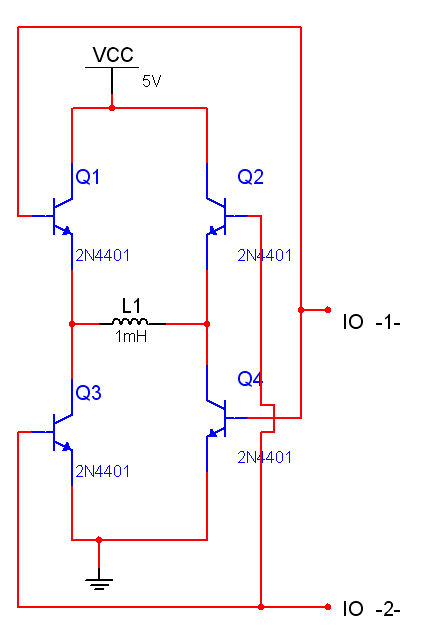
What I want to do, is make a stepper controller that only needs one pin(and maybe a common clock or something for all of them...). I was thinking accomplishing this by using an 8-bit·serial-to-parallel IC. I figure using all 8 ouputs of the S-to-P·converter to drive my dual H-brdige for each motor. Currently, I'm using 2n3904 NPN bipolar transistors as a small H-bridge, but I realized that this is not a good configuration. If you'll refer to the attached schematic, you'll know what I'm talking about. When IO 2 is high, the voltage drop across the base of Q1 and the emitter of Q4 is about 1.2V, Plus the inductance of the motor winding. However, the voltage drop across the base of Q4 and the emitter, is only 0.6V and no inductance. I'm afraid of this inductance getting in the way of driving Q1 as fast, and that there is a high voltage drop across it to begin with. I know using MOSFETs would be better, but this is only a simple concept prototype after all. For now, would it be better to use PNP transistors as a replacement for Q1 and Q2 and have all the bases of each transistor seperate on their own IO pin? This way for a dual H-bridge, I will need 8 pins total, which is exactly what an 8-bit SP converter has. Any suggestions welcome.
What I want to do, is make a stepper controller that only needs one pin(and maybe a common clock or something for all of them...). I was thinking accomplishing this by using an 8-bit·serial-to-parallel IC. I figure using all 8 ouputs of the S-to-P·converter to drive my dual H-brdige for each motor. Currently, I'm using 2n3904 NPN bipolar transistors as a small H-bridge, but I realized that this is not a good configuration. If you'll refer to the attached schematic, you'll know what I'm talking about. When IO 2 is high, the voltage drop across the base of Q1 and the emitter of Q4 is about 1.2V, Plus the inductance of the motor winding. However, the voltage drop across the base of Q4 and the emitter, is only 0.6V and no inductance. I'm afraid of this inductance getting in the way of driving Q1 as fast, and that there is a high voltage drop across it to begin with. I know using MOSFETs would be better, but this is only a simple concept prototype after all. For now, would it be better to use PNP transistors as a replacement for Q1 and Q2 and have all the bases of each transistor seperate on their own IO pin? This way for a dual H-bridge, I will need 8 pins total, which is exactly what an 8-bit SP converter has. Any suggestions welcome.
bmp
821K
Comments
<http://www.mcmanis.com/chuck/robotics/tutorial/h-bridge/index.html>
Not specifically for steppers, but a nice H-bridge.
Nick
▔▔▔▔▔▔▔▔▔▔▔▔▔▔▔▔▔▔▔▔▔▔▔▔
Never use force, just go for a bigger hammer!
The DIY Digital-Readout for mills, lathes etc.:
YADRO
The driver is almost ready to use! Just ask!
Saluti Joerg
The thing quite clever is using opto-couplers. So the whole noisy power part is completely isolated. A drawback is, that you can't PWM it with high frequencies (1kHz max, IIRC). I'll try it with faster OCs (HCPL4502 or such).
I'm in the process of building a traversal table feed (DC-motor) for my (not already ex-manual) surface grinder. Prop-driven, of course!
May add two steppers for down and side feed, so I don't have to be standing by. Grinding is a sloooow process ...
Nick
▔▔▔▔▔▔▔▔▔▔▔▔▔▔▔▔▔▔▔▔▔▔▔▔
Never use force, just go for a bigger hammer!
The DIY Digital-Readout for mills, lathes etc.:
YADRO
The voltage drop was exactly the reason to develop this circuit! The transistors are always operating in saturation
which means minimal losses!
Make sure the base current of the power transistors is about three times the minimal base current needed: Ib = Ic / hFE *3
The base current of the steering transistor is about (Uout - 1,4V) / Rbase. The circuit works similar to a Darlington configuration
with the advantage of a much lesser saturation voltage (~0.3V instead of ~1.5V!!).
I hope this helps
Saluti Joerg
- the lack of ANY base resistors!!!
- the high side output voltage will be lat least 0.7V below the output voltage of the chip output and even more with the
resistor needed in series so i would say the high side voltage is at least 1V below the chips output voltage -> 2.3V!!
- so finally voltage you may use is 2.3v minus 0.3V = ~2.0V!!
My circuit will reach 3.3V - (2*.3V) = 2.7V (if the resistors are well chosen!!)
Saluti Joerg
Any chance you might sell off a few steppers to someone in Austex?
I might be able to help with driving them. I suspect a 2n3904 is going to be a bit light for driving a reasonable sized stepper.
I have used some 2n2222 for driving a floppy drive stepper at 12V. But these are still quite low current motors.
Since you have some efficient FETs available, I'm sure they would be better. Do you know if your steppers are bipolar or
unipolar?
Paul
Post Edited (bot-man) : 2/8/2008 10:34:01 PM GMT
-> good night!
Saluti Joerg
There are two ways to deal with this when driving the motor at higher-than-rated voltages:
1. Use current feedback to PWM-regulate the drive circuitry, thus keeping the current at or below spec.
2. Use a resistor in series with the coil.
Number two is the simplest (but least power-efficient) method. Use a voltage supply that's four or five times the motor's rated voltage. The resistor should be chosen such that at full saturation, the motor is drawing its rated current. In your case, the voltage across the coil leads would be 3.3V. But here's why it works: When the coil is first switched on, it's drawing no current, so the voltage drop in the series resistor is zero, and the coil "sees" the entire (higher) supply voltage. This forces current into the coil more quickly. As the coil current rises, the voltage drop through the resistor also increases, and the voltage across the coil drops until it reaches its rated value.
Here is an article that explains these issues in more detail.
-Phil
Post Edited (Phil Pilgrim (PhiPi)) : 2/8/2008 10:58:11 PM GMT
Bot-man,
Yes, I'd be willing to sell MANY of these off to you. You may not have read my previous post, but I will be picking up ~225 steppers of all different sizes. It's a hell of a deal too... $450 for THESE:
http://cgi.ebay.com/ws/eBayISAPI.dll?ViewItem&item=110217746972&ssPageName=ADME:X:RTQ:US:1123
Let me know which ones you want and I'll sell them for fairly cheap. I gotta make SOME money for my time and investment.
Thanks guys!
Adding a capacity in parallel of the series resistor speeds up the current thru the coil. But care has to be
taken for the right value of the C. The C has to be discharged during the off time of the coil.
Rule of thumb: C * R * 5 = off time.
Saluti Joerg
However for driving steppers you don't really want an H-bridge, you really want a bunch of current sinks, which N-channel fets can do very nicely. As long as you turn them fully on, and do it fairly quickly, you can pass much more current through them than an equivalent bi-polar transistor with very little voltage drop. And as the other Phil in this thread points out what you really want is to put a fixed current through the stepper windings which is best done with something called a 'chopper' circuit.
--Chuck
--Chuck
Oh, yeah, Joerg - Wanna trade some brand new steppers for some of those completed dual H-bridges, above? These motors have an '89 date code, but they haven't ever been used - still in styrofoam casing.
I've seen many power mosfets using a series resistor. However, I have never understood WHY. It seems that the resistor limits the amount of current going into the gate, thereby increasing the transistion time between off and fully on. The only thing I can think of is to reduce any resonance between the capacitance of the gate and stray inductance in the wire?
-Phil
Never used one, though.
Edit: The current for the I2C-version is 0.8A peak. No external drivers possible. Just read through the manual. Interesting (ramping, position, almost stand-alone, etc) but not what I need.
Nick
▔▔▔▔▔▔▔▔▔▔▔▔▔▔▔▔▔▔▔▔▔▔▔▔
Never use force, just go for a bigger hammer!
The DIY Digital-Readout for mills, lathes etc.:
YADRO
Post Edited (Nick Mueller) : 2/10/2008 4:15:42 PM GMT
for unipolar motors i use the circuit shown in the attachment.
to PhiPi:
six wire motors can also driven as bipolar motors using the two wires at the "endpoints". This doubles the resistance but it works.
Saluti Joerg
-Phil
Simple applications can use simple drivers (like the ones i have posted).
Sophisticated devices need sophisticated drivers!! (LM298 etc.)
So probably it would be a good idea to explain what you plan to do!
Saluti Joerg