

How to choose resistors in a Programmable Gain Amplifier
 Paul Baker
Posts: 6,351
Paul Baker
Posts: 6,351
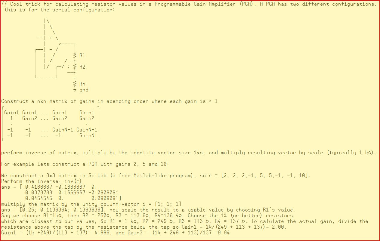
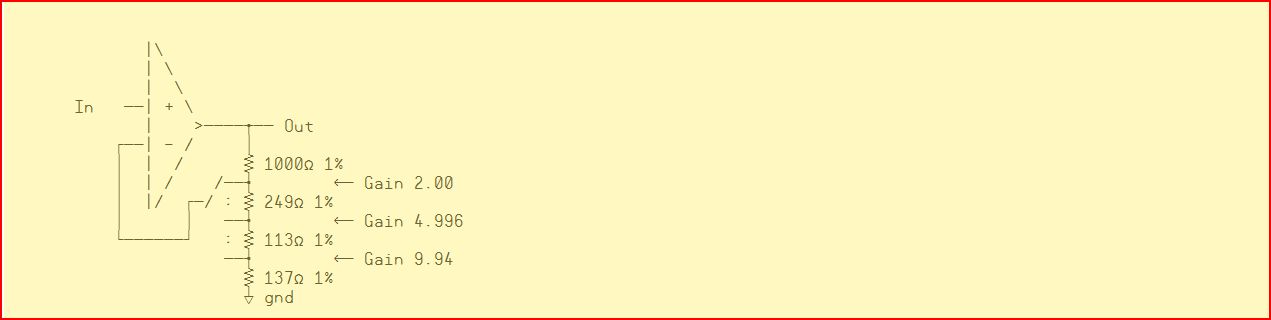
Sometimes analog amplifiers with multiple gains are needed in a design, the most straight forward way to do this is to construct circuits in parallel and choose which amplified signal to measure. But if you need the gains to be·strongly correlated with each other then parallel is a bad choice. Not only is there mismatch from the ratio resistors, but differences in offset voltage between multiple amps, bias current etc all effect each gain in seperate ways. Programmable Gain Amplifiers help with this by providing many different gains on one amplifier by using a resistor ladder and an analog multiplexer. The series method has the advantage of allowing analog multiplexors with a significant resistance because it is a very low current path. Calculating the resistor values can be daunting, but there is a simple solution using linear algebra, you don'tneed to understand how it works, just cookbook it and you'll get the answers.


Here's the article which discusses it: http://www.edn.com/contents/images/6356067.pdf
▔▔▔▔▔▔▔▔▔▔▔▔▔▔▔▔▔▔▔▔▔▔▔▔
Paul Baker
Propeller Applications Engineer
Parallax, Inc.
Post Edited (Paul Baker (Parallax)) : 2/4/2008 8:18:30 AM GMT
Here's the article which discusses it: http://www.edn.com/contents/images/6356067.pdf
▔▔▔▔▔▔▔▔▔▔▔▔▔▔▔▔▔▔▔▔▔▔▔▔
Paul Baker
Propeller Applications Engineer
Parallax, Inc.
Post Edited (Paul Baker (Parallax)) : 2/4/2008 8:18:30 AM GMT
1263 x 801 - 118K
1271 x 320 - 31K
Comments
or r = [noparse][[/noparse]1, 1, 1; -1, 4, 4; -1, -1, 9] , perform inv(r) * [noparse][[/noparse]1; 1; 1]*1000 and we get R1=1000, R2=600, R3=200, R3=200 or the 1% resistors 1000, 604, 200, 200 and remembering to add the 1 the real gains are 1.996, 5.01 and 10.02.
Alternatively a 590 ohm resistor can be combined with a 10 ohm resistor to produce exact gains (within tolerence).
So, is this stuff going over peoples heads or this just isn't applicable to what people are doing?
▔▔▔▔▔▔▔▔▔▔▔▔▔▔▔▔▔▔▔▔▔▔▔▔
Paul Baker
Propeller Applications Engineer
Parallax, Inc.
Post Edited (Paul Baker (Parallax)) : 2/5/2008 2:18:20 AM GMT
The photodiode amplifier that my company sells has 86 distinct gains set by 2 dip switches. Both stages can switch between either straight or split T feedback. The first stage has a transconductance gains of 4000 to 28000 ohms in steps of 4000 and in split T mode from 40000 to 180000 ohms in steps of 40000. The second stage has non-inverting gains from 1 to 8 and also in split T from 10 to 45 in steps of 5. These days 0.1% film resistors are readily available. Much easier than it used to be to find them in thru-hole.
A second stage of optimization can often find a best combination of resistor values. For example, one choice for an x8 non-inverting amplifier might be 69.8k with 10k. But a better combination is 105k with 15k. It gets harder when optimize whe there are more ratios to match.
▔▔▔▔▔▔▔▔▔▔▔▔▔▔▔▔▔▔▔▔▔▔▔▔
Tracy Allen
www.emesystems.com
▔▔▔▔▔▔▔▔▔▔▔▔▔▔▔▔▔▔▔▔▔▔▔▔
Paul Baker
Propeller Applications Engineer
Parallax, Inc.
Post Edited (Paul Baker (Parallax)) : 2/8/2008 4:59:19 AM GMT
I do respect the art of achieving the high bandwidth. That is an accomplishment! I do know that rail to rail op amps will never have their full bandwidth near the rails. You may need an booster module to give the +/- 12 or 15 volts, so that the op amps or other circuits can run near the center. But clamp it so that it does not overload the ADC. Almost all rail to rail input op amps have quirks, that have to do with the dual input stage, switching over from the pnp to the npn amplifiers. Differences in bias currents, offsets, and bandwidth. But rrio op amps sure make ee design easier in many situation.
My multi-gain amplifier is heavily compensated and is designed for accuracy at DC, not for high frequency or pulses. For the highest gains and accuacy, it uses a CAZ rail to rail ouput op amp. On a single supply will pull down to within 5 millivolts of ground, but for some things that is too much, and I have to add a -1.2 volt (V-) supply so that it can go all the way to zero and with decent bandwidth there. Increased bandwidth comes with narrowing the gain choices, more attention to the compensation, and a different choice of op-amp. Always trade offs.
▔▔▔▔▔▔▔▔▔▔▔▔▔▔▔▔▔▔▔▔▔▔▔▔
Tracy Allen
www.emesystems.com
▔▔▔▔▔▔▔▔▔▔▔▔▔▔▔▔▔▔▔▔▔▔▔▔
Paul Baker
Propeller Applications Engineer
Parallax, Inc.
As to the bandwidth, I did a course on opamps last year. Rf/Rs + 1 works really well at low frequencies but it starts to fall apart at higher frequencies. But by the sounds of it you already know that
If you can build this for a reasonable price I will buy one.