

Noise on the pins?
 Chuck McManis
Posts: 65
Chuck McManis
Posts: 65
Hi everyone,
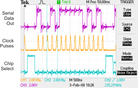
New propellor user here and having a lot of fun so far. My requirement at the moment is to write out serial data to a chip using a few of the I/O pins. I was getting sort of weird results (every now and then a bit would be just wrong) and so I finally hooked everything up to my scope to get a closer look. I've attached a picture of that hookup. Basically I've got a Chip Select (active low), a clock line, and a serial data input line. (latched on the rising edge of the clock).
What you can see from the picture is that there is a lot of ringing on the pins. Now the device in question is a digital to analog converter so its by passed to the gills (basically a 10uF in parallel with a .1uF on both the Analog Vcc and the Digital Vcc). And most of the time the chip correctly gets the right value, but occasionally a bit is off. And in my application losing a sample is pretty obvious to the user.
So any thoughts on how one might go about quieting down the signal lines? (Yes I'm working with a propellor board that has a wireless breadboard and I expect some ringing from that setup but I'd rather not spin a PCB just to test out if the propellor can cut it in terms of driving this DAC chip.)
--Chuck
563 x 360 - 44K
Comments
Maybe a wild guess.. are you using scope probes..?
I use a Fluke 123 Scopemeter 20MHZ to trouble shoot stuff and when I use the std multimeter probes we get signals
looking like that...
cheers ron mel oz
Yes, I am using probes. Since the noise seems to be in the 40+Mhz range I can understand that you would not see it on a 20Mhz scope (mine is 200Mhz) and I can BW limit the probe to get a cleaner display but I'm really trying to understand the electrical properties of the Propellor. Since the noise is large enough to give me a bit flip now and then I want to address it prior to commiting to a PCB. I'm wondering what the output drivers look like on the Propellor and if perhaps I need some resistors to match the impedence better with 5V logic.
--Chuck
If this doesn't improve things, you may have inadequate supply bypassing. Make sure to put a 0.1uF ceramic cap with short leads between Vdd and Vss right at the supply pins on the Prop and on your DAC. Also, make sure you're meeting the setup and hold time specs for the DAC chip. (Judging from your trace image, though, this doesn't look like a problem.)
-Phil
Attached some screen shots of a job on the bench.
100KHZ clk to a MAX490·· RS422/485 transceiver chip· pulsing and reading a SSI absolute encoder.
(This setup works awesome... been working for weeks not one error in reading..
We send the data to a PC verify it and continue ...)
If I disconnect the GND probe and just use the alligator clip on Gnd I get fairly different results as you can see on the clk signal especially.
One smooth clk signal is measured with proper COM connection OV ( + alligator 0V connection· as well)
the other CLK signal is fairly noisy· similar to what your seeing...
The Fluke 123 has a separate COM connector this needs to be used on jobs like this to get a nice clean signal.
Cheers··· Ron Mel OZ
As already noted, the signal edges are very fast. The ringing is not on the pins per se, but a combination of the inductance and capacitance in the external circuit. Those white prototyping plugboards have quite a bit of capacitance, on the order of 100pf from one to the next and also to the ground plane. The circuit board traces contribute the inductance. There is also that loop of wire for the 'scope ground.
The Prop demo board has a fat ground stake right next to the Propeller, and with that, one can remove the 'scope ground wire and touch the ground ring on the scope probe to that stake while touching the tip of the probe right to a Prop pin. The pin itself will not have the kind of bounce you observed.
There has been quite a bit of discussion of this kind of topic in relation to sigma-delta conversion, where that extra inductance and capacitance has to be eliminated.
Hey, are you the Chuck McManis who explored the inner workings of the BASIC Stamp I?
▔▔▔▔▔▔▔▔▔▔▔▔▔▔▔▔▔▔▔▔▔▔▔▔
Tracy Allen
www.emesystems.com
--Chuck