

Basic Stamp 1 - unable to communicate
 Browny
Posts: 15
Browny
Posts: 15
Hi, I posted on here about a week or 2 ago about a problem I was having with uploading a program to Basic stamp module. I have no experience in this as the board I am using is from a controller for a radio telescope and all im trying to do it update the controllers firmware. I have since found out that I have Basic Stamp 1 and I needed an adaptor for it. I found a schematic to make one which I have done, and when I try to Run the program using the BASIC Stamp Windows Editor version 2.4 software it still does not recognise any Stamp hardware as being attached. Am I using the right software or should I be using something else for Stamp 1? The set up I have is there is a Basic Stamp 1 Module (BS1-IC) that is not part of a programming board, would this be the problem?
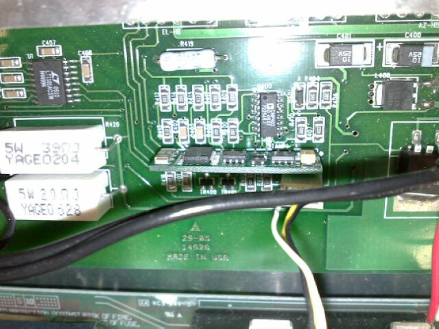
I have attached a photo of the board to help make what I said a bit clearer hopefully.
I have attached a photo of the board to help make what I said a bit clearer hopefully.
640 x 480 - 59K
Comments
On your PC, are you connecting to the serial port, or the parallel port? Which adapter did you build? Is the target device powered when you’re trying to identify/program it?
▔▔▔▔▔▔▔▔▔▔▔▔▔▔▔▔▔▔▔▔▔▔▔▔
Chris Savage
Parallax Tech Support
Interesting you should mention the BS1-IC not being powered, as that's the aspect I was investigating this morning. When using either the Parallax BS-1 Serial Adapter, or one made from the Parallax supplied schematic, I can see no provision for powering it. It almost seems as if you MUST use a Parallax or other carrier board, and insert the BS1-IC into it before using the serial adapter. Just a while ago, I was looking at all of the various schematics to see if it was possible that the BS-1 Serial Adapter was using parasitic power, but that does not seem to be the case.
How would you go about supplying power to the BS-1-IC for programming (stand alone) without using a carrier board?
The only "clean" way I can see to do it is to replace the 3-pin SIP connector with a 4-pin SIP connector so you can pick up Vin at pin 1 on the BS1-IC. Vss is extant, so on the "new" 4-pin connector you would have (in order):
Vin Vss PCO PCI
1 2 3 4
all in a line on one SIP connector. If RESET (pin 6) is required as it is on the BS-2's , that's another issue altogether.
Regards,
Bruce Bates
▔▔▔▔▔▔▔▔▔▔▔▔▔▔▔▔▔▔▔▔▔▔▔▔
There is no pleasure in having nothing to do;
the fun is in having lots to do, and not doing it!
···The BASIC Stamp 2 (for example) has only 4 lines that connect a PC to it for programming (SIN, SOUT, ATN and GND). Regardless of the board used you still have to have the module powered. That power is not supplied by the programming interface regardless of the board used.· Same goes for the BS1.· I was trying to verify that the poster was powering his circuit. Take care.
▔▔▔▔▔▔▔▔▔▔▔▔▔▔▔▔▔▔▔▔▔▔▔▔
Chris Savage
Parallax Tech Support
Post Edited (Chris Savage (Parallax)) : 1/31/2008 10:15:33 PM GMT
I'm not trying to beat a dead horse, honestly.
What you say is quite true, and this whole thing goes even deeper than that. I went back and re-read all the documentation I'd gathered this morning. At least by virtue of the following quotation, extracted from the web page which contains the DIY BS-1 Serial Adapter schematic, the BS1-IC isn't even covered in the usage of the adapter!
quote
The BASIC Stamp 1 Serial port adapter plugs between the BASIC Stamp Rev D (or the BS1 Carrier Board) in the serial cable as shown below. It's so simple we don't even ship documentation with the hardware!
end quote
Although it may work with the previously suggested modifications in place on the BS1-IC, I guess it's not officially supported, or that's what I glean from that quotation since the BS1-IC has been omitted. The two platforms that are supported both have built-in facilities for supplying power. Therein probably why this issue hasn't been seen before in quite this form.
Regards,
Bruce Bates
▔▔▔▔▔▔▔▔▔▔▔▔▔▔▔▔▔▔▔▔▔▔▔▔
There is no pleasure in having nothing to do;
the fun is in having lots to do, and not doing it!
I think we’re on two different tracks here. The point I was making regarding power applies to any microcontroller capable of in-circuit programming. Generally speaking the programming interface would not provide power so as not to interfere with the power systems of the connected circuitry. The BS1 Serial Adapter is intended for any BASIC Stamp 1, regardless of format. We published the schematic to help those who wish to build their own interface, however that schematic and/or the adapter are independent of the supply feeding the device. Bear in mind that most development boards make connecting power and the programming connection easier, however it certainly is not required and is merely trying to mimic the target configuration in most cases.· I guess I'm not sure what additional information you need.· Should we provide more details of connecting the adapter to the BS1-IC?
▔▔▔▔▔▔▔▔▔▔▔▔▔▔▔▔▔▔▔▔▔▔▔▔
Chris Savage
Parallax Tech Support
I suspect something like the following caveat or warning should suffice:
When using the BS-1 Serial Adapter or the serial adapter schematic provided below, to program a BS1-IC, it is necessary for the user to provide appropriate power to the BS1-IC in whatever manner is fitting. When the serial adapter is used with other BS-1 formats on Parallax carrier boards, the power is an included feature of the carrier board itself, so no further or additional power connections are necessary.
Regards,
Bruce Bates
▔▔▔▔▔▔▔▔▔▔▔▔▔▔▔▔▔▔▔▔▔▔▔▔
There is no pleasure in having nothing to do;
the fun is in having lots to do, and not doing it!
I will see what we can do and pass along your suggestions. Take care.
▔▔▔▔▔▔▔▔▔▔▔▔▔▔▔▔▔▔▔▔▔▔▔▔
Chris Savage
Parallax Tech Support
Note: Though it is not shown, power must be connected to the BS1 to program it.
A similar thing is said for the BS2-type connection in the manual.
I see that this statement is not made on the downloadable schematic mentioned, so we'll update that.
Thanks for pointing that out.
▔▔▔▔▔▔▔▔▔▔▔▔▔▔▔▔▔▔▔▔▔▔▔▔
--Jeff Martin
· Sr. Software Engineer
· Parallax, Inc.