

PCF8566 and VIM828-DP voltage or timing problem?
 CableGuy67
Posts: 38
CableGuy67
Posts: 38
Hello. I hope someone can help me out here.
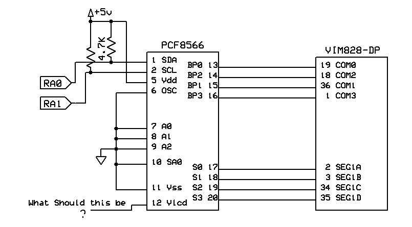
I have a test circuit wired up on my PDB that uses 2 pins from the SX28 for I2C to a PCF8566P to drive a VIM828-DP LCD 14-seg display. It's wired up as shown (actually the I2C bus also is wired to an EEPROM on the board) and I seem to be getting my information into the PCF. If I tilt the board and look at the LCD from an angle I can see my character but the OFF segments aren't really going off.
My assumption is that using Vss for the Vlcd is a poor choice, well one that doesn't work anyhow. Based on the datasheet the working voltage generated is Vdd-Vlcd. So what should Vlcd be? My thought is that I divide the +5vdc and use a part of it for the LCD voltage. I just wish I had more info on the VIM...
Links to the datasheets:
PCF8566 datasheet
VIM-828-DP datasheet
Any help would be most appreciated. I hope I'm just missing something simple here. I seem to be close. The data sent to the PCF should look like a 'db' back to back and sharing the vertical. I'm only concerned with the first digit for now.
Thanks,
Mark
▔▔▔▔▔▔▔▔▔▔▔▔▔▔▔▔▔▔▔▔▔▔▔▔
mirk handwrote
admire nth work
805 x 445 - 3K

Comments
This won't help you one iota, except possibly to assuage your conscience. As I've said to others who have offered "datasheets" like that from other manufacturers, for my money that's a set of mechanical or electro-mechanical drawings and nothing more. A data sheet contains voltages, current, timings, temperatures, and other data appropriate to the device being referenced. How they get away with calling those datasheets, is beyond me.
Sorry I couldn't be of more assistance.
Regards,
Bruce Bates
▔▔▔▔▔▔▔▔▔▔▔▔▔▔▔▔▔▔▔▔▔▔▔▔
There is no pleasure in having nothing to do;
the fun is in having lots to do, and not doing it!
[noparse]:)[/noparse] Thanks, I've been thinking the same thing ever since I've had these LCD's. It's a shame too, They would work out great for the system design representations they are meant to display. Lot's of triangular shapes. Well I'm not giving up yet. I've got extras to play with...
The DIP packages are for testing. They may not all make it.[noparse];)[/noparse] The final package is supposed to be 4 of these each driven by the surface mount version (PCF8566) that has 32 segment outputs.
Mark
▔▔▔▔▔▔▔▔▔▔▔▔▔▔▔▔▔▔▔▔▔▔▔▔
mirk handwrote
admire nth work
Mark
▔▔▔▔▔▔▔▔▔▔▔▔▔▔▔▔▔▔▔▔▔▔▔▔
mirk handwrote
admire nth work
Post Edited (CableGuy67) : 1/29/2008 12:23:48 PM GMT