

howto use a basic stamp to run a electromagnetic
 nemesiswes
Posts: 17
nemesiswes
Posts: 17
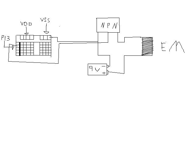
Hi, i'm new to this but i was wondering if it was posible to run a electromagnet off of the stamp by using a transistor connected to battery and the basic stamp to control the on off of the transistor to control the pulse's from the electromagnet .
kinda like the one i just made
(I·made an attachment, it·should work)
not sure if it's wired right and forgot to add the resistors to but that's the overall diagram of how it would work
and i was wondering, can a basic stamp on the homework board turn the electromagnet off and on at atleast 1000 times a second or what is the fastest it can? and if not what can.
last, is there anything i should have done that i didnt. thx for·all comments
640 x 512 - 18K
Comments
Finally, make sure your transistor can handle the current demanded by the coil. You would be good to use a power darlington transistor like the TIP120. Or you could use a power MOSFET, like the IRF510. The IRF510 would be your best way to do it; instead of a base, collector, and emitter, you have a gate, drain, and source. You still connect it the same for this circuit, with these substitutions:
base --> gate
collector --> drain
emitter --> source
I'm not on my own computer so I don't have access to any schematic-drawing software but I'll try to make a schematic for you when I get home. Incidently, what are you building this for? When I was a kid I made a similar circuit with the Basic Stamp and three MOSFETs and three coils. It was a coil gun that could launch a nail a few feet across a room.
on the exact circuit parameters.
The time required for the current to completely build up is roughly
3*L/R
where L is the inductance in henries, and R is the total circuit
resistance in ohms (coil resistance plus any external current limiting
resistor).
Assuming equal rise and fall times for the current in the coil,
3* (L/R) has to be 500 microseconds or less in order to be able to
turn it on and off 1,000 times per second.
It will depend on whether you are switching amps or milliamps.
Do you know any specifics on the inductance and current?
phil
to phil,· well what if i just lower the power, so like say the coil goes from 5 amps to say 100 mili amps or something like that so that instead of going completly off it just lower's the power, i am sure the formula you gave still works but would i have to change a little or not because when the current increases it would time for the magnetic field to rise to fulland then when the power goes down the field goes down and that would take time . so could i still use that one you gave.· srry but i don't know to much about some of this stuff lol, and the whole engine is supposed to be a dc motor
have to be specially designed for that mode.
A DC motor with a sufficiently low armature inductance can be
switched at the rate you wanted.
The equation I listed gives the time needed for the current to
change by approximately 95 percent. In two time constants
it will change by 86 percent.
Are you trying to design a motor that can be driven in a PWM
(pulse width modulated) mode?
What is the reason for having to switch the motor power 1,000
times per second?
phil
how it turns out.
Excuse my lack of knowledge in circuitry since I am more of a programmer. But my project is similar in needs to nemesiswes. I am looking towards using my BS2x with 3 separate electromagnets (iron and coils). My goal is simply to have the strength of electromagnet flux or if not, just turning it on and off.
If someone could provide a schematic of the circuitry of with one electromagnet then that would be absolutely helpful!
Thank you. [noparse]:D[/noparse]