

Vector graphics on cro
 stevenmess2004
Posts: 1,102
stevenmess2004
Posts: 1,102
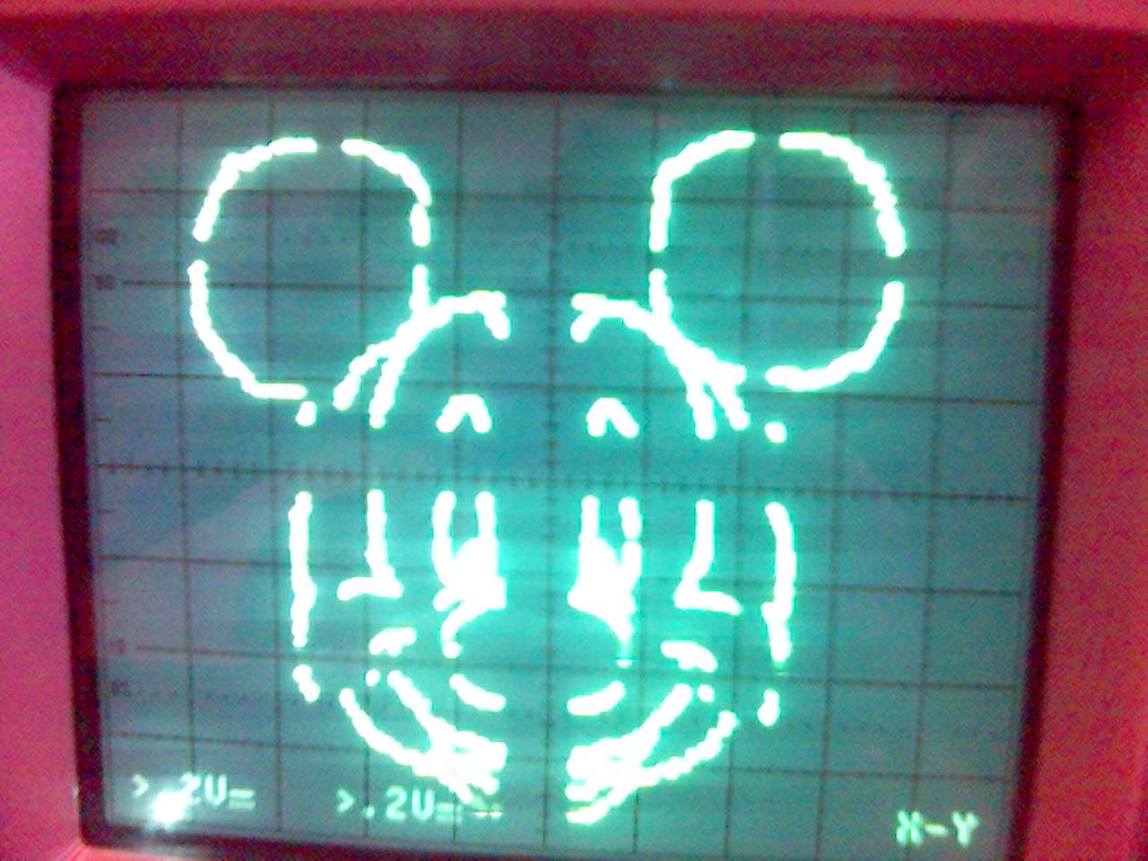
This is a project that I did with a friend for a tafe course. It displays pictures on a CRO in x-y mode.
1280 x 960 - 120K

Comments
Got to see your doing well with the Prop..
How did you get the signal onto the cro via composite video input on the CRO
Ron Nollet
Steven
Now if you wanted to be REALLY retro you could make pong. I'd love to see that on a oscilloscope.
Bean.
▔▔▔▔▔▔▔▔▔▔▔▔▔▔▔▔▔▔▔▔▔▔▔▔
- - - - - - - - - - - - - - - - - - - - - - - - - - - - - - -
www.iElectronicDesigns.com
·
<http://www.timefracture.org/vectclk.html>
Nick, not wanting to make your job look bad!
▔▔▔▔▔▔▔▔▔▔▔▔▔▔▔▔▔▔▔▔▔▔▔▔
Never use force, just go for a bigger hammer!
The DIY Digital-Readout for mills, lathes etc.:
YADRO
▔▔▔▔▔▔▔▔▔▔▔▔▔▔▔▔▔▔▔▔▔▔▔▔
Michael Park
PS, BTW, and FYI:
To search the forum, use search.parallax.com (do not use the Search button).
Check out the Propeller Wiki: propeller.wikispaces.com/
In which case using the 1K and 2K resistor ladder DAC method would probably help.
I disassembled a small TV to tinker with like VECTREX but didn't finish anything interesting on it yet.
Nick, I like that clock. I'm glad I didn't have to design the board for the vector graphics generator. Its so much easier with a Prop.
The gaps are because the resistor values I was using at that stage were not exactly the right values. We just used the closest value that we had and then changed them if necessary (such as 1k2 instead of 1k). This got rid of the most visible gaps. I was going to make a text driver for it but I run out of time.
Bean, I thought about doing something like Pong but I run out of time and I don't have a cro to test it on at home. Otherwise I'd probably do it.
Steven