

H-Bridge Question
 Drone
Posts: 433
Drone
Posts: 433
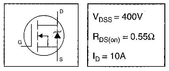
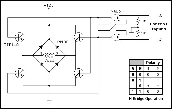
I want to drive a two winding bipolar stepper motor with the propeller with a pair of H-bridges. I have a bunch of spare IRF740 MOSFETS (see figure attached). I want to use the MOSFETS in-place of the NPN transistors in the attached H-Bridge schematic.
Question: Since the IRF740 MOSFETs have an internal zener across the drain and source, do you think I can eliminate the 1N4004 protection diodes in the H-bridge schematic? This is my first time dealing with these parts.
Edit: In my first post I forgot to add credit for the H-Bridge.jpg circuit attached to Jason Johnson. I scraped the diagram from his excellent stepper tutorial page (circa 1998) at:
http://eio.com/jasstep.htm.
Thanks, David
Post Edited (Drone) : 1/20/2008 5:16:52 PM GMT
549 x 233 - 23K
551 x 349 - 31K
Comments
I typically do this driving with common LM358 opamps to translate the logic levels while I power the opamp from a voltage doubler made up of a 555 timer.
BTW, yes you can discard the external diodes as the internal diodes are much faster anyway than a common rectifier diode. Also as an alternative the IRF3205 are quite cheap and feature a very low RdsON of 0.008R vs 0.55R plus a lower effective Vgsth (although most mosfets are never low enough to run directly from logic level drive and handle high currents).
*Peter*
Regards, David
i would prefer to use N-FETs to ground and P-FETs on the +12 side!
This way you get a simple and reliable H-bridge without any bulky driver.
Saluti Joerg
Edit: Also, if you use an ordinary op-amp to drive the MOSFET, be aware that a MOSFET gate is not quite like a CMOS digital logic input! It has hundreds of times more gate capacitance than a digital input and can require a lot of drive current to properly drive it at higher frequencies. Op-amps won't provide enough current (at high frequencies) to drive a MOSFET, and so although the circuit will appear to work, you will burn out your MOSFETs under load. HOWEVER, if you limit yourself to low frequencies (a few hundreds to 1 or 2 thousand Hz) then you should be ok with an op-amp drive.
Post Edited (Dennis Ferron) : 1/19/2008 8:56:03 PM GMT
Dennis: I agree and there is merit in adding diodes at the source of interference although we are talking about running stepper motors which mostly operate at much lower frequencies. I have designed high-speed micro-stepping controllers before and I prefer that the pcb is mounted as close as possible to the motor as long leads generate EMI anyway. It's all much neater and more serviceable when everything is on the pcb sealed inside the box.
I would disagree however as regards to opamps not being able to drive mosfets at high frequencies. The humble lm358 may not be up to the task but there are a 101+ pin compatible opamps (aka adsl drivers, buffers, etc) ready to put their hands up.
*Peter*
After a short view in some of the lie collections (data sheets) here some facts.
The reverse recovery time of a real fast diode is about 30ns where as the reverse diode of FET's have around 100ns!
The stored charge is about 10nC and the reverse diode of FET's have more than 100nC!
That is why i recommend extra diodes for H bridges.
Joerg
David
FYI, I've got the IRF3205 simulated in LTSpice/SwitcherCADIII (free from www.linear.com/designtools/software/). Attached is a .zip file containing (1) the subcircuit definition file that models the IRF3205, (2) an example circuit for LTSpice that tests Vgsth, and a text file explaining how to use 3rd party subcircuit definitions with LTSpice.
Thanks, David