

New (and final) issue with the dynamo powering BS1 (old issue solved in previou
 Blake
Posts: 74
Blake
Posts: 74
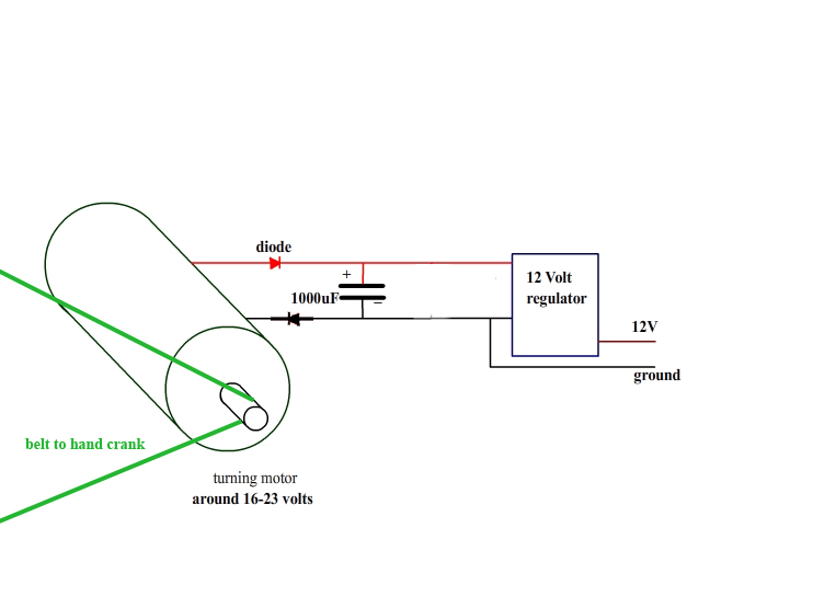
I am powering a BS1 with a small DC motor turned by a hand crank geared to it with a belt. So far this is working with the following setup (see image). The only action the basic stamp performs is to powers on a stepper motor for about 1 second out of every five. The rest of the time it is pausing. When I stop turning the crank, all functions cease. When I turn the crank again, all functions resume. Everything cool, right? Well I am encountering some massive feedback through the motor/dynamo. As i turn the crank and the stepper activates, when the stepper comes on, there is huge tension on my hand crank and it becomes 3-4 times harder to crank. I have taken apart all of my mechanism and found that this tension is coming from my dynamo. If I stop turning (and the basic stamp shuts off) and then begin turning again, the tension is gone, and the dynamo is easy to turn again. Any idea whats going on? I just added a diode on the ground to try and somehow fix this but it didn't work.

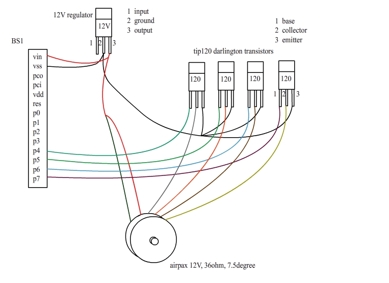
and my stepper/BS1 setup:

Thanks,
Blake
and my stepper/BS1 setup:
Thanks,
Blake
763 x 555 - 95K
763 x 555 - 117K
Comments
The stepper is going to use many times more current than the BS1. So of course it is going to be harder to crank when the BS1 engergizes the stepper motor.
Bean.
▔▔▔▔▔▔▔▔▔▔▔▔▔▔▔▔▔▔▔▔▔▔▔▔
- - - - - - - - - - - - - - - - - - - - - - - - - - - - - - -
www.iElectronicDesigns.com
·
Thanks,
Blake
The motor is 12V 36 ohms. That is 333mA per coil @ 12V = 4 Watts.
If you put a 36 ohm resistor in series with each coil that make the current half (or 167mA), but also you are losing half the voltage in the resistor. So it's like running the motor coil from 6 volts which is 167mA * 6 = 1 watt. So you are using half the current (make the generator easier), but you are only getting 1/4 the power to the motor.
What would really help is a buck (switching) regulator because alot of power is being lost there. Or find a stepper that uses less power, or use a PWM or chopper circuit to drive the stepper coils.
Bean
▔▔▔▔▔▔▔▔▔▔▔▔▔▔▔▔▔▔▔▔▔▔▔▔
- - - - - - - - - - - - - - - - - - - - - - - - - - - - - - -
www.iElectronicDesigns.com
·
Sorry, the computer that I normally use to draw schematics with is tied up at the moment so....
Note: Make sure that·the drive transistors to your stepper motor have pull-down resistors on their base connection.
·
▔▔▔▔▔▔▔▔▔▔▔▔▔▔▔▔▔▔▔▔▔▔▔▔
Beau Schwabe
IC Layout Engineer
Parallax, Inc.
Post Edited (Beau Schwabe (Parallax)) : 1/17/2008 6:41:23 PM GMT
Does the device need to be actually powered by the crank, or do you just want the device to only operate when cranked?
For an example, I had a friend who's son was getting a little pudgy and playing·a lot of videao games. HE asked me if I could make him a bicycle powered TV. I told him no way could your kid really power a TV. What I did was take an exercise bike and using the output fom that made a "credit" system. If he pedaled fast enough he would begin buidling credits. At a certain speed, he would get 1 minute of TV time for 1 minute of work. If he pedaled harder, he could get up to 3:1 credits. The TV would run for as long as he had credits.
Anyway, I was just wondering if your situation was at all similar.
▔▔▔▔▔▔▔▔▔▔▔▔▔▔▔▔▔▔▔▔▔▔▔▔
www.madlabs.info - Home of the Hydrogen Fuel Cell Robot
(what some would argue as an addiction), but, to answer your question, it is important
that everything be powered by the dynamo. I frequently use electronics in my art
projects, however, i strive to be a more earth conscious person, and i really can't
justify having a piece plugged in 24/7 when it is possible for the machine to sustain
itself. It also allows me to move it to places "beyond the grid," so to speak.
blakefallconroy.com
Do you mean something like a 10K resistor between the BS1 and the base of the transistors? Is this to prevent misfiring of the transistors?
You should already have some sort of current limiting resistor between the BS1 and the base of the transistors.
With the circuit that I provided, the BS1 will turn OFF and the inputs to the transistors will be floating.
What is typically done in this circumstance to prevent floating inputs is to use a pull-down resistor from the transistor
bases to GND (for NPN) ... VDD (for PNP). The resistor value, usually is pretty high 100K to 1Meg is typical.
You just want something that's going to provide 'some' amount of bias to keep the transistors off should the inputs be floating.
▔▔▔▔▔▔▔▔▔▔▔▔▔▔▔▔▔▔▔▔▔▔▔▔
Beau Schwabe
IC Layout Engineer
Parallax, Inc.