I for some reason cannot get the SX-28 to run on a separate project board other than the actual programming board. it is like the chip gets no power or something. can someone help me please.
I am going to add them, but i am limited on how many resistors i have right now. I am just in the testing stages. Still cannot figure out why there is no output from the chip when i put it on a normal project board.
ok, i put the chip on my test project board and hooked it up the way it is hooked up on the other project board. Here is a pic of it. Still not working [noparse]:([/noparse]
Your voltage divider does not look like it's doing what you want. You don't seem to have the 10K connected to ground, so I'm guessing you have +12 into MCLR\ and probably Vdd too -- check with a meter. Let me suggest you run to your local RadioShack and get a 7805.
i have a 22k resistor dropping the voltage down to 5 volts. so i am going to need to buy an external regulator to hook up the chip on another board? radio shack is my local supply store and i get major discounts since i buy so much from there. Should i still need a regulator or is there any possible way to power it without the regulator?
there is a 10K resistor coming from 5v+ going to the MCLR. then the 5v+ goes to the Vdd. I have already programmed the chip, but I just need to run it on a stand alone board.
If you have a solid +5V, a bypass cap 0.1uF from Vss to Vdd, and a 10K from Vdd to MCLR then it should run.
I'm not sure what you doing with +12 to 14 through a resistor to Vdd ???
P.S. You might also try adding BOR26 to the device line. This will help if you have a supply that doesn't rise quickly.
i need the 12v to power 2 motors but it all has to come from the same power supply. If I remove the chip from my project board and put it on the programming board, it works perfectly. I don't see the difference [noparse]:([/noparse]
From your posts it still isn't quite clear how you are powering the SX28 chip. It appears that you are trying to use the 22K resistor to drop the 12v down to 5v. Is that what I am seeing in the picture?? If so I would expect it not to work so it is doing what it should.
You should have a clean 5V supply for the SX28 chip. That is already present on the programming board for the SX28. When you put the SX28 on the protoboard can you temporarily take the ground and 5V connections from your programming board and connect those to your breadboard. If that makes the difference then the power supply is the first problem. If it works then get at least a 7805 voltage regulator and a couple filtering caps.
If Radio Shack doesn't have those on hand then look for some electronics gadgets headed out to the trash. You'd be surprised to see just how many will have a 7805 regulator that you can pull out for free.
It's often difficult to get started but once you successfully get through a few projects it does get easier. There are a lot of people on this forum of all levels of experience and they are very helpful.
Are you going to run everything off of a single battery or is it a 12v wall supply? Please post how what you are using to power your circuit and what voltages you want it to supply. Since you mention motors it is also useful to determine the current requirements of those. If you are powering the motors through a smaller regulator that could cause you problems down the road.
Dude... The datasheet for the SX28 specifies 5.5 volts MAXIMUM supply voltage. That means you MUST have a regulated power supply.
Also, where is your clock? Did you setup the chip to run on the internal RC oscillator? If so, you do know that runs at something between 3 and 5 KHz, not the standard Mhz right? If you want fast, you must also supply the clock.
Read the datasheet.
▔▔▔▔▔▔▔▔▔▔▔▔▔▔▔▔▔▔▔▔▔▔▔▔
---
James Newton, Host of SXList.com james at sxlist,com 1-619-652-0593 fax:1-208-279-8767
SX FAQ / Code / Tutorials / Documentation: http://www.sxlist.com Pick faster!
The circuit will be mounted inside a car running from a 12 to 14v 10 amp supply so I can only run off of 1 power source. i just tried what you said by taking the chip out of the programming board and putting it in my stand alone project board then running the wires from the programming board to power the chip. It did not work [noparse]:([/noparse] I tried the 10k resistor to the MCLR, tried putting another cap between Vdd and Vss, I even took the same resistor and LED off the programming board and put it on the project board. nothing worked [noparse]:([/noparse] I got my ohm meter and checked to ensure all 28 pins were getting a good connection and they were. I am stumped and I really want to get this project done before friday.
There is no timing in the programming. just if's then's and else's and a few goto's. The chip is getting 5v DC!!!! It is NOT getting 12v. The 12 volts is cut down by the 22k resistor dropping it to 5v. I don't even think there is a pause statement in there now.
Post Edited (eagletalontim) : 1/16/2008 4:26:47 AM GMT
Running it in a car (NOISY power) means you should _definitely_ use a regulator and filter circuit; maybe even an LC circuit upstream of the power supply to cut down on the noise. It is not the SX's fault here; you've stated that it works in one place but not another -- the only thing that changed are your connections. You really should get a regulator and consider reviewing and reconnecting everything else. One of my friends was having trouble today until he pulled his circuit apart and reconnected -- it started working.
ok, i will get one tomorrow from radioshack. If possible, could someone post a schematic on how to power up the SX without the programming board like what i need. I am not the best at figuring out things before i burn them up I would greatly appreciate it!
If there are any documents about the SX that have schematics, I would love to see how to power and work this chip apart from having to keep it in the programming board.
With the regulator, can I use it to drop the power down from 12 - 14v to 5v, then control the output to be 12 - 14v to the motor using transistors without causing problems with the regulator? I have never used a regulator before and am still learning as much as I can.
Have a look at the schematic that's attached; the power supply is very generic and you can use the 7805 where I have the LF50 (an LDO regulator) as long as your input is greater than 7 volts.
Yes, you can use transistors or MOSFETs to control your high current devices using the SX to provide the control input to them.
eagletalontim said...
There is no timing in the programming. just if's then's and else's and a few goto's. The chip is getting 5v DC!!!! It is NOT getting 12v. The 12 volts is cut down by the 22k resistor dropping it to 5v. I don't even think there is a pause statement in there now.
Ok, can you explain to me exactly how you are getting 5V to the SX28 chip through a 22K ohm resistor?? I just don't see how that is possible. Please post a schematic. Even if you measured 5V at some point if you are relying on a resistor to bring down the power to 5V it would be completely unstable and jump all over the place. From everything i've read so far this is the most likely thing that is causing the problem.
Can you at least try to use to 5V from your programming board as a test to confirm or deny that the power is or is not the problem?? Until you do that all the other troubleshooting will be a waste of time. Stable power to the chip is one of the basics.
Running everything off a single 12v source (or battery) is not a problem at all. For any other voltages you just derive them from the 12v source. Some of the options you can use (There are others):
- Small DC/DC convertor
- Voltage regulator (780x series are very common)
- Several large rectifier diodes in series (I would not recommend this for your application)
- A couple low ohm (hi wattage) resistors setup as a votlage divider with a Zener diode as a reference. (I would not go this route either)
In any of the cases above you'll want to add some filtering caps on both the input and output of the circuit to generate your 5V. Caps are cheap and you will need them if you are going to put them in your car.
I think your best bet is to just use a 5v regulator with some caps to power the SX processor.
eagletalontim said...
With the regulator, can I use it to drop the power down from 12 - 14v to 5v, then control the output to be 12 - 14v to the motor using transistors without causing problems with the regulator? I have never used a regulator before and am still learning as much as I can.
The answer to your question above is yes! It is one of the most common ways to handle this.
To control your motor there is a variety of options. First, how do you need to control your motor?? Do you need just a simple on/off control? Do you need to be able to vary the speed? Also, do you need to control the direction?
If you just need simple on/off control then you might just want to use a relay. There are quite a few examples of this for use with the BASIC Stamp. You would control them with the SX chip the same way. An example can be found at:
For variable speed control in one direction you can consider MOSFET's. If you need variable control in both directions then start looking at H-Bridge circuits.
I finally got the chip to boot up with the regulator. i wound up having to put a 1k resistor from the 12v source to the input of the regulator or it would burn it up. found that out the hard way [noparse]:([/noparse]
Yes, I just need to turn the motors on/off I think i figured out that circuit using an NPN and a PNP. The PNP is rated at 15A so i should not have any problems with it i hope
One more thing. does anyone know a company that can print boards for a reasonable cost? It is a pain in the butt to have to solder all those wires to where they need to go
Glad to hear that you've been able to get your project going. Instead of using a 1K resistor to feed the voltage regulator you might want to use a few 1N5401 diodes in series to bring the voltage down a bit before going into the regulator. Each one of those diodes will give about a .7V drop. Four of those diodes in series will drop the 12v to something closer to 9V which is just fine for most 5V regulators. Make sure to add some sort of filtering on the power lines too.
At the very least you would want to add something like a 10uf electrolytic cap across the output of the 7805 voltage regulator. Note that some caps are polarized and can't be connected backwards. The electrolytic is polarized so make sure the 1 gotes to ground and the other side goes to +5v. You should also add a .1uf or .01uf cap directly across the power leads on the SX28 processor. As a general rule I always put a .1uf or .01uf cap at every IC right at it's supply pins. In simple terms the capacitors will help smooth out any spikes that can and will occur on the power lines. For reliable operation it is just good practice to add them from the start. Without them you can get random glitches in the system that are hard to troubleshoot.
The LC filtering that JonnyMac mentioned is another step above this. It would entail adding an inductor in series with one of the power input lines and then a cap across the power going into the voltage regulator. You may or may not need to go this route.
Some searches on Google on power filtering, LC circuits, etc should turn up more detailed info about this.
ok, i added an electrolytic cap to the Vdd and the ground and it works good [noparse]:)[/noparse] one problem i have now is that the output of the transistors is not enough to run the motors [noparse]:([/noparse] I need help figuring this one out. I have the output of the chip going to a 100k resistor that goes to the base of a switching NPN. The collector is connected to a 10K resistor then to ground. The emitter of the NPN is going to the ground of the PNP transistor. The collector of the PNP is going to the motor and the emitter is going straight to the voltage in without restrictions. I wish I could draw up a schematic, but i have not found a program to help me do that. What am i doing wrong to not be able to power the motors?
It sounds like the resistors are way too high and it's hard to picture exactly how you've got this connected. If you need a simple schematic drawing package there is an excellent one you can download for free from:
One thing I have found and try to stay away from is running anymore voltage to the 5volt regulator than needed. Running 12volts into the 5 volt regulator creates alot of heat.
As far as your transistor setup your base resistors are way to high and·should be·based on the transistor specs. If you had a schematic so we could see what you are trying to do·and would·help. NPN transistors are for current sink(switching ground) and PNP transistors for switching positive voltages. The one thing you have to watch with a PNP transistor is the fact that there will be a postive voltage on the base and if you are running 12volts through the transistor you·will end up with that voltage back at the SX this is a bad situation. It is always best to have positive trigger out of the SX to a NPN then to a PNP or just NPN only for current sink to the motor.
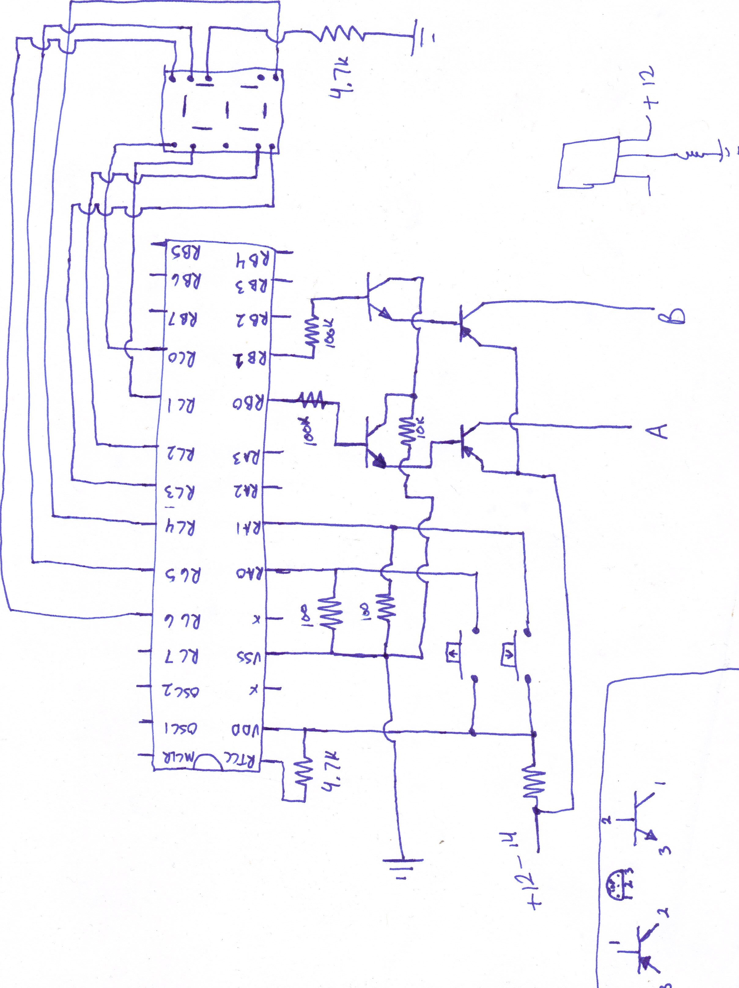
I attached a schematic with designed with the program above on how i have the chip hooked up. It may not be exact for the power up of the chip, but the output is exact on pin RB0. I need to keep it a positive output because the motors are already grounded to the body of the car. This is the last bug i have to work out before i can test it full scale [noparse]:)[/noparse] Hopefully you can help me!
Note :
The NPN transistor is a small switching transistor.
Sorry. i just downloaded that program and put that schematic together all within 15 minutes. never used it before. No, there is no -12 in my car :P
R1 is limiting the current to the chip. The collector of the PNP is connected before the 1k so that there is no resistance except for the resistance of the PNP transistor.
There is a 10k going to the MCLR, i just forgot to put that in the schematic.
I am trying to build this circuit to not have moving parts and want to keep it as small as possible so I don't want to use relays. Would radioshack have an FET that can handle 10A? I am still learning about more about transistors so I have limited knowledge on what to use. I was under the impression that transistors were kind of like switches with no moving parts.

 eagletalontim
Posts: 1,399
eagletalontim
Posts: 1,399

Comments
Your voltage divider does not look like it's doing what you want. You don't seem to have the 10K connected to ground, so I'm guessing you have +12 into MCLR\ and probably Vdd too -- check with a meter. Let me suggest you run to your local RadioShack and get a 7805.
Post Edited (JonnyMac) : 1/16/2008 3:37:06 AM GMT
Bean.
▔▔▔▔▔▔▔▔▔▔▔▔▔▔▔▔▔▔▔▔▔▔▔▔
- - - - - - - - - - - - - - - - - - - - - - - - - - - - - - -
www.iElectronicDesigns.com
·
I'm not sure what you doing with +12 to 14 through a resistor to Vdd ???
P.S. You might also try adding BOR26 to the device line. This will help if you have a supply that doesn't rise quickly.
Bean.
▔▔▔▔▔▔▔▔▔▔▔▔▔▔▔▔▔▔▔▔▔▔▔▔
- - - - - - - - - - - - - - - - - - - - - - - - - - - - - - -
www.iElectronicDesigns.com
·
From your posts it still isn't quite clear how you are powering the SX28 chip. It appears that you are trying to use the 22K resistor to drop the 12v down to 5v. Is that what I am seeing in the picture?? If so I would expect it not to work so it is doing what it should.
You should have a clean 5V supply for the SX28 chip. That is already present on the programming board for the SX28. When you put the SX28 on the protoboard can you temporarily take the ground and 5V connections from your programming board and connect those to your breadboard. If that makes the difference then the power supply is the first problem. If it works then get at least a 7805 voltage regulator and a couple filtering caps.
If Radio Shack doesn't have those on hand then look for some electronics gadgets headed out to the trash. You'd be surprised to see just how many will have a 7805 regulator that you can pull out for free.
It's often difficult to get started but once you successfully get through a few projects it does get easier. There are a lot of people on this forum of all levels of experience and they are very helpful.
Are you going to run everything off of a single battery or is it a 12v wall supply? Please post how what you are using to power your circuit and what voltages you want it to supply. Since you mention motors it is also useful to determine the current requirements of those. If you are powering the motors through a smaller regulator that could cause you problems down the road.
Good luck,
Robert
Also, where is your clock? Did you setup the chip to run on the internal RC oscillator? If so, you do know that runs at something between 3 and 5 KHz, not the standard Mhz right? If you want fast, you must also supply the clock.
Read the datasheet.
▔▔▔▔▔▔▔▔▔▔▔▔▔▔▔▔▔▔▔▔▔▔▔▔
---
James Newton, Host of SXList.com
james at sxlist,com 1-619-652-0593 fax:1-208-279-8767
SX FAQ / Code / Tutorials / Documentation:
http://www.sxlist.com Pick faster!
There is no timing in the programming. just if's then's and else's and a few goto's. The chip is getting 5v DC!!!! It is NOT getting 12v. The 12 volts is cut down by the 22k resistor dropping it to 5v. I don't even think there is a pause statement in there now.
Post Edited (eagletalontim) : 1/16/2008 4:26:47 AM GMT
With the regulator, can I use it to drop the power down from 12 - 14v to 5v, then control the output to be 12 - 14v to the motor using transistors without causing problems with the regulator? I have never used a regulator before and am still learning as much as I can.
Yes, you can use transistors or MOSFETs to control your high current devices using the SX to provide the control input to them.
Ok, can you explain to me exactly how you are getting 5V to the SX28 chip through a 22K ohm resistor?? I just don't see how that is possible. Please post a schematic. Even if you measured 5V at some point if you are relying on a resistor to bring down the power to 5V it would be completely unstable and jump all over the place. From everything i've read so far this is the most likely thing that is causing the problem.
Can you at least try to use to 5V from your programming board as a test to confirm or deny that the power is or is not the problem?? Until you do that all the other troubleshooting will be a waste of time. Stable power to the chip is one of the basics.
Running everything off a single 12v source (or battery) is not a problem at all. For any other voltages you just derive them from the 12v source. Some of the options you can use (There are others):
- Small DC/DC convertor
- Voltage regulator (780x series are very common)
- Several large rectifier diodes in series (I would not recommend this for your application)
- A couple low ohm (hi wattage) resistors setup as a votlage divider with a Zener diode as a reference. (I would not go this route either)
In any of the cases above you'll want to add some filtering caps on both the input and output of the circuit to generate your 5V. Caps are cheap and you will need them if you are going to put them in your car.
I think your best bet is to just use a 5v regulator with some caps to power the SX processor.
Good luck,
Robert
The answer to your question above is yes! It is one of the most common ways to handle this.
To control your motor there is a variety of options. First, how do you need to control your motor?? Do you need just a simple on/off control? Do you need to be able to vary the speed? Also, do you need to control the direction?
If you just need simple on/off control then you might just want to use a relay. There are quite a few examples of this for use with the BASIC Stamp. You would control them with the SX chip the same way. An example can be found at:
www.parallax.com/dl/docs/cols/nv/vol1/col/nv6.pdf
Also, be sure to read through the old Nuts&Volts articles on the Stamps and SX. They are very helpful. You can get them at:
www.parallax.com/Resources/NutsVoltsColumns/tabid/272/Default.aspx
For variable speed control in one direction you can consider MOSFET's. If you need variable control in both directions then start looking at H-Bridge circuits.
Hope these help,
Robert
Yes, I just need to turn the motors on/off I think i figured out that circuit using an NPN and a PNP. The PNP is rated at 15A so i should not have any problems with it i hope
One more thing. does anyone know a company that can print boards for a reasonable cost? It is a pain in the butt to have to solder all those wires to where they need to go
Glad to hear that you've been able to get your project going. Instead of using a 1K resistor to feed the voltage regulator you might want to use a few 1N5401 diodes in series to bring the voltage down a bit before going into the regulator. Each one of those diodes will give about a .7V drop. Four of those diodes in series will drop the 12v to something closer to 9V which is just fine for most 5V regulators. Make sure to add some sort of filtering on the power lines too.
Good luck,
Robert
The LC filtering that JonnyMac mentioned is another step above this. It would entail adding an inductor in series with one of the power input lines and then a cap across the power going into the voltage regulator. You may or may not need to go this route.
Some searches on Google on power filtering, LC circuits, etc should turn up more detailed info about this.
Robert
www.expresspcb.com/
A schematic will help illustrate just how you have things connected and make it easier for others to comment and help.
Some other links that may help are:
http://www.windmeadow.com/node/4
http://hades.mech.northwestern.edu/wiki/index.php/Driving_using_a_single_MOSFET
As far as your transistor setup your base resistors are way to high and·should be·based on the transistor specs. If you had a schematic so we could see what you are trying to do·and would·help. NPN transistors are for current sink(switching ground) and PNP transistors for switching positive voltages. The one thing you have to watch with a PNP transistor is the fact that there will be a postive voltage on the base and if you are running 12volts through the transistor you·will end up with that voltage back at the SX this is a bad situation. It is always best to have positive trigger out of the SX to a NPN then to a PNP or just NPN only for current sink to the motor.
Kevin
▔▔▔▔▔▔▔▔▔▔▔▔▔▔▔▔▔▔▔▔▔▔▔▔
Note :
The NPN transistor is a small switching transistor.
The PNP is a TIP42 rated at 40V, 10A
▔▔▔▔▔▔▔▔▔▔▔▔▔▔▔▔▔▔▔▔▔▔▔▔
Shawn Lowe
Maybe I should have waited to do that......
No 10K on the MCLR pin.
The PNP transistor has the emitter and base connected together ???
I would look at using a FET or relay for motor control. The TIP42 has pretty low gain.
Bean.
▔▔▔▔▔▔▔▔▔▔▔▔▔▔▔▔▔▔▔▔▔▔▔▔
- - - - - - - - - - - - - - - - - - - - - - - - - - - - - - -
www.iElectronicDesigns.com
·
R1 is limiting the current to the chip. The collector of the PNP is connected before the 1k so that there is no resistance except for the resistance of the PNP transistor.
There is a 10k going to the MCLR, i just forgot to put that in the schematic.
I am trying to build this circuit to not have moving parts and want to keep it as small as possible so I don't want to use relays. Would radioshack have an FET that can handle 10A? I am still learning about more about transistors so I have limited knowledge on what to use. I was under the impression that transistors were kind of like switches with no moving parts.