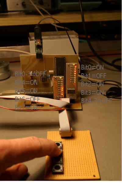
Stange behaviour of OUTA....
After some starting difficulties and some very helpful tips from forum members, here something i am wondering about:
If i put data on outa an am using a variable direct the result makes sense to me; if i use the variable via pointer the bits are reversed:
i.e. variable N := 13 Result direct: Bit0=1, Bit1=0, Bit2=1, Bit3=1, Bit4..7=0
Result via pointer Bit0..3=0, Bit4=1, Bit5=1, Bit6=0, bit7=1
Here a program with this behaviour:
Does anybody know why this happens?
Saluti Joerg
If i put data on outa an am using a variable direct the result makes sense to me; if i use the variable via pointer the bits are reversed:
i.e. variable N := 13 Result direct: Bit0=1, Bit1=0, Bit2=1, Bit3=1, Bit4..7=0
Result via pointer Bit0..3=0, Bit4=1, Bit5=1, Bit6=0, bit7=1
Here a program with this behaviour:
'test2.spin
'

VAR byte N
    long Stack[noparse][[/noparse]10]


PUB test2
  dira[noparse][[/noparse]0..7]~~
  N := 0
  cognew(outx(@N), @Stack)

  repeat
    outa[noparse][[/noparse]7..0] := N
    waitcnt(clkfreq / 1_000_000 * 10_000 + cnt)
    N := ina[noparse][[/noparse]11..8]


PUB outx(AdrInVar)
  dira[noparse][[/noparse]23..16]~~

  repeat
    outa[noparse][[/noparse]23..16] := long[noparse][[/noparse]AdrInVar]
Does anybody know why this happens?
Saluti Joerg


Comments
-Phil
I have tried to change form byte to long, thats why long[noparse][[/noparse]AdrInVar] shows up in the code.
Thank you Phil.
Buona notte Joerg
Joerg, can it be that you are just LOOKING upside down? Pins 16..24 are at the upper side of the Prop...
is it because the direction you are assigning to your LED's reads...
[noparse][[/noparse]23..16]
...instead of...
[noparse][[/noparse]16..23]
... ?
▔▔▔▔▔▔▔▔▔▔▔▔▔▔▔▔▔▔▔▔▔▔▔▔
Beau Schwabe
IC Layout Engineer
Parallax, Inc.
OUTA[noparse][[/noparse]7..0] := N
as well..
[b]CON[/b]

  [b]_clkmode[/b] = [b]xtal[/b]1 + [b]pll[/b]16x
  [b]_xinfreq[/b] = 5_000_000

'test2.spin
'

[b]VAR[/b] [b]byte[/b] N
    [b]long[/b] Stack[noparse][[/noparse]10]


[b]PUB[/b] [b]test[/b]2
  [b]dira[/b][noparse][[/noparse]0..7]~~
  N := 0
  [b]cognew[/b](outx(@N), @Stack)

  [b]repeat[/b]
    [b]outa[/b][noparse][[/noparse]7..0] := N
    [b]waitcnt[/b](clkfreq / 1_000_000 * 10_000 + [b]cnt[/b])
    N := 13


[b]PUB[/b] outx(AdrInVar)
  [b]dira[/b][noparse][[/noparse]23..16]~~

  [b]repeat[/b]
    [b]outa[/b][noparse][[/noparse]23..16] := [b]long[/b][noparse][[/noparse]AdrInVar]
-Phil
I haven't really read this thread properly but isn't it a problem if you declare a byte variable before a long as the longs need to be word aligned. What would happen I think is that the stack would use the same address as the byte. Declare longs, then words, then bytes and you won't get any alignment problems.
*Peter*
Steven
VAR byte N
    long Stack[noparse][[/noparse]10]
This here will give you more issues:
VAR byte X, Y, N
    long Stack[noparse][[/noparse]10]
I still suspect - as yesterday - Joerg was just looking upside down
Post Edited (deSilva) : 1/12/2008 12:19:23 PM GMT
I simply messed up P16..P23 -> PC7..PC0 and P24..P31 -> PD7..PD0
Thanks anyway for all the tips!
I will modify my MCU module for UMDL right now!
Saluti Joerg
The doc can be found here: www.systech-gmbh.ch -> UMDL -> Parallax -> P8X32A-D40
Saluti Joerg
No! The UMDL system (formerly called HC(S)08 system) uses a simple 2x36pin header (72pol, 0.1"). This is enough for 8 8bit ports (as most other MCU's are using a port nomenclature). The MCU modules are fitting on base plate (with 10 pin headers and additional stuff). The original idea was to create a system for different MCU's (different families and different manufacturers).
So i can change the MCU if for some reason the chosen one does not fit anymore. The system is totally modular and based on the 10 pin header philosophy. So i have developed RS232 interfaces as well as stepper motor drivers and a lot more modules (and also a lot more in mind). But this is only one part of the story: Each module (if once tested!!!!!!!!!) has the schematics ready for being used in the final design. And this is true for the software also: My EBS08 (Einfaches Betriebs System 08) is also modular, consisting on a TIC generator for controlling simple tasks and a lot of modules around. They are (at the time being) written in ASM or C for the Freescale HC(S)08 MCU's, but step by step i will write these modules for the Propeller chip.
In fact i have realized a lot of my projects using UMDL and EBS08 for hardware and software development and i have used the basic modules to make the final design. This is a fast and secure approach and i just LOVE it.
Saluti Joerg
PS. If somebody is interested have a look here: www.systech-gmbh.ch -> UMDL