

Spin Stamp Module with INEX-1000?
 Rayman
Posts: 16,460
Rayman
Posts: 16,460
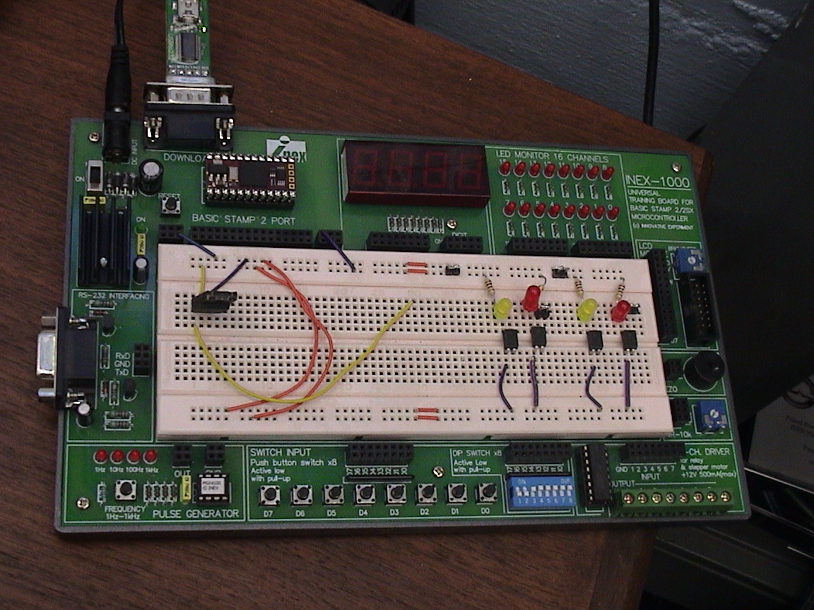
I just tried putting a Spin Stamp Module in my old INEX-1000 and connecting with a USBto232 device...
But, it seems that it doesn't work...· Anybody got the Spin Stamp Module to work with INEX-1000?
I can't find any wiring diagrams for the INEX-1000...· But, I guess I could take it apart and figure out what's wrong...
But, it seems that it doesn't work...· Anybody got the Spin Stamp Module to work with INEX-1000?
I can't find any wiring diagrams for the INEX-1000...· But, I guess I could take it apart and figure out what's wrong...
1152 x 864 - 557K
Comments
you need to connect a prop clip to the 4 pads on the side of the spin stamp.
regards peter
In that respect it behaves like a basic stamp.
Series protecting resistors of·1k on all I/O pins is necessary because of the
5V logic devices on the INEX board.
regards peter
·
Loaded deSilva's pin toggling code and it makes a LED blink right...
Too bad they didn't hook up a serial interface...· Looks like they thought about it...
BTW: Have you noticed that my "pin toggling" allows you to insert a LED between any two pins!! Think about it!
Depending on the clock you can even omit a resistor (when it toggles < 1 sec)
just not for programming. Here are the propeller pin assignments:
CON
·
· 'clock settings for spin stamp
· _clkmode = xtal1+pll8x
· _xinfreq = 10_000_000
·
· debugPort = 2 '0=none, 1=propeller TX/RX, 2=spin stamp SOUT/SIN/ATN
·
· '//Spin stamp debug pin assignments
· stampSOUT = 16 'serial out (pin 1 of spin stamp)
· stampSIN· = 17 'serial in· (pin 2 of spin stamp)
· stampATN· = 18 'digital in (pin 3 of spin stamp, when activated, do reboot)
· '//Propeller system pin assignments
· propSCL = 28 'external eeprom SCL
· propSDA = 29 'external eeprom SDA
· propTX· = 30 'programming output
· propRX· = 31 'programming input
VAR
· long atnStack[noparse][[/noparse]10]······· 'stack for monitoring ATN pin
·
PUB main
· 'monitor ATN pin (optional)
· if debugPort == 2
··· cognew(atnReset,@atnStack)
PUB atnReset
· repeat 'loop endlessly
··· if (debugPort == 2) AND (INA[noparse][[/noparse]stampATN] == 1)
····· reboot
If you monitor the ATN pin, then if you toggle DTR of the serial port ON and OFF,
the spin stamp reboots, just like a basic stamp.
regards peter
Actually, the spin stamp datasheet says: do not connect for these pins, but the transistors
that do the level shifting are present on the spin stamp.
regards peter
Post Edited (deSilva) : 1/10/2008 7:56:19 PM GMT
What a pain... I wish they'd have put in a 5 MHz crystal...
▔▔▔▔▔▔▔▔▔▔▔▔▔▔▔▔▔▔▔▔▔▔▔▔
Paul Baker
Propeller Applications Engineer
Parallax, Inc.