

Can I get comments on this 120v AC to 6.3v(edited) DC power supply?
 MarkS
Posts: 342
MarkS
Posts: 342
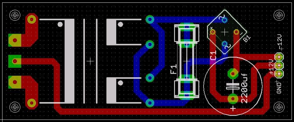
I need this for a project I'm working on. A wall wart cannot be used due to the design. Therefore, I need to convert mains power to +12v and -12v DC. The main controller board will have a 5v and 3.3v regulator and required circuitry and this power supply will supply those regulators. This is my first time dealing with AC, so I'm a little nervous and want to make sure that everything is correct.
The parts list should be pretty obvious, except for the transformer. The transformer is a Tamura 3FS-524 120v to 12v.
Any comments and criticism will be appreciated, but space is limited, so please don't bump up the parts list with anything that isn't 100% necessary.
Post Edited (MarkS) : 1/8/2008 12:21:08 AM GMT
Comments
-Phil
Post Edited (Phil Pilgrim (PhiPi)) : 1/7/2008 9:46:34 PM GMT
▔▔▔▔▔▔▔▔▔▔▔▔▔▔▔▔▔▔▔▔▔▔▔▔
- Rick
Back to work...Just out of curiosity, why would I get 17 volts from the rectifier when the transformer is outputting 12 volts and the diodes in the rectifier drops voltage?
Post Edited (MarkS) : 1/7/2008 11:02:13 PM GMT
▔▔▔▔▔▔▔▔▔▔▔▔▔▔▔▔▔▔▔▔▔▔▔▔
- Stephen
Not really an option due to size.
While looking at Digi-Key for a new transformer, I found one from the same supplier, with the same data sheet and foot print. It outputs 6.3v from 120v, but I'd still like to know why I was told differently above about the last transformer. How did you guys come up with 17 volts?
The fuse appears to be connected to nothing or is across the output of the transformer leads... Dead short!
take a look at the attachment of how it looks like this transformer need to be connected to get +-12volts.
Post Edited (LilDi) : 1/7/2008 11:37:44 PM GMT
Or this attachment.
▔▔▔▔▔▔▔▔▔▔▔▔▔▔▔▔▔▔▔▔▔▔▔▔
Paul Baker
Propeller Applications Engineer
Parallax, Inc.
Post Edited (Paul Baker (Parallax)) : 1/8/2008 12:33:58 AM GMT
LilDi is right. I wasn't paying attention to your ground or to your fuse. I just saw the two windings connected in parallel. If what you really want are both plus and minus outputs, you will need separate caps. LilDi shows a half-wave configuration. For better efficiency, the configuration shown below (attached) would give you full-wave rectification for each output. In any event, the earlier comments about rectified voltage remain the same. (The reason for the higher voltage is that the transformer specs are for RMS voltage. But a capacitor-input filter under no load will provide the peak voltage as DC.)
-Phil
Post Edited (Phil Pilgrim (PhiPi)) : 1/8/2008 12:35:00 AM GMT
So the corrected version of my PS would actually output roughly 9vDC. Interesting.
Thanks again. More work to do.
-Phil
So, to recap...
The last design I posted would work? Or will I blow something up? Also, using the formula Paul posted, I'll be getting 8.9v and -8.9v DC with a transformer rated for 6.3v, correct?
What will be the maximum load each output has to drive? This is important in picking the final capacitor value, so the minimum output voltage due to ripple doesn't drop below the input voltage required by your regulators.
BTW, what is the negative output being used for?
'Just noticed: The transformer end of your fuse is way too close to the chassis ground!
-Phil
The negative voltage is for the OpAmps, but after looking at some diagrams with a LM34 and ADC, I probably wont be needing them.
Phil can probably give you a more accurate fuse type.
Post Edited (LilDi) : 1/8/2008 2:49:16 AM GMT
Phew!
-Phil
-Phil
▔▔▔▔▔▔▔▔▔▔▔▔▔▔▔▔▔▔▔▔▔▔▔▔
'Still some PropSTICK Kit bare PCBs left!
▔▔▔▔▔▔▔▔▔▔▔▔▔▔▔▔▔▔▔▔▔▔▔▔
PLEASE CONSIDER the following:
Do you want a quickly operational black box solution or the knowledge included therein?······