

Call for comments for a USB-Plug with 3.3V source
 Joerg
Posts: 91
Joerg
Posts: 91
Hi
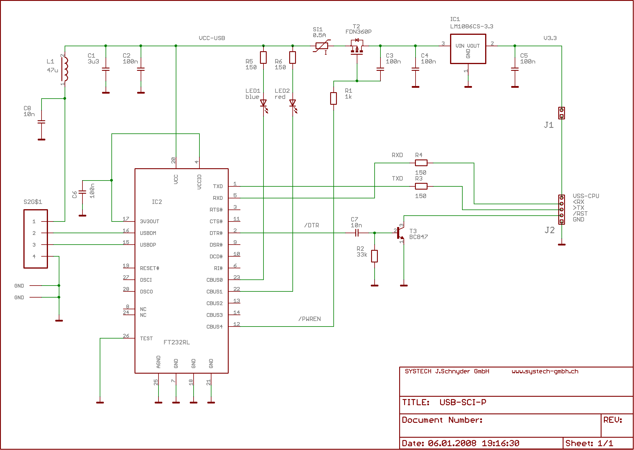
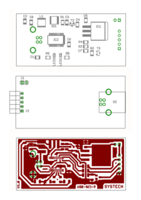
since i have noticed, that (maybe) there is a certain request for a USB-device with a voltage regulator on board,
i have done the schematics and layout for it (EAGLE! see the red and green lines). The next step is to create a little
PCB to put to plugs on it having so the possibility to run the prop tool on one USB interface and a other USB interface
for communicating after downloading.
Any comments are welcome
Saluti Joerg
2168 x 1538 - 39K
282 x 400 - 25K
Comments
Whatever you do, I recommend that you don't go right to a production PCB, but spend some time with either a breadboard or proto PCB and a scope to fine-tune this important part of your circuit.
-Phil
The 5V are nice as well for the breadboard as for some veroboard buid-ups. As most things should run stand -alone eventually they will be powered by 4.8 to 6 Volts, be it from the 4D plug or from an external battery, but thus ned a regulator anyhow..
On the other hand I also build a small "all-in-one-bridge" fitting on top of a breadboard inserted Propeller to minimize wiring... There is a small DPAK regulator on it.
Well, what I wanted to say: Yes and no... It could be nice, depending on the circumstances..
N.B.: Header Pins.. After a lot of experiences with fitting and unfitting things onto solderless breadboards, I should recomend you use double row headers. It will become much more robust.
Post Edited (deSilva) : 1/6/2008 8:25:02 PM GMT
@Phil:
- I have attached three pdf files with a simulation of the Power On sequence. If the PWREN# pin of the device is set as
input there is the possibility of a spike (ON.pdf) adding a resistor (R4=4.7k) makes it almost disappearing (ON1.pdf).
Is it this effect you meant?
- Since i have a LPKF milling machine i can mill my prototypes by myself! This saves a lot of costs, time and nerves!
@deSilva:
- i will change the socket to a 2x5row type.
Saluti Joerg
I think I tried the pullup, but didn't get as satisfactory results as your simulation indicates. But there's a bigger problem, as I hinted at in my prior post: Upon powerup, PWREN# does not stay high until the FT232R is enumerated, but pulses low multiple times during the chip's reset sequence, rendering its intended function nearly useless. The reason this occurs in the 'RL but not the 'BM version is that in the 'RL PWREN# is assigned to a general-purpose I/O pin, which has to be configured as part of the reset sequence. This is one reason I resorted to the voltage detector circuit: to delay past the low pulses.
Below, I've attached some GIFs of the PWREN# line during powerup and enumeration for you to look at, with detailed views of the pulses I referred to...
-Phil
Addendum: Here's a transcript of my exchange with FTDI tech support:
Then later, from FTDI:
And finally,
Here is the circuit they proposed:
I tried it, and responded thus:
I have no record of an answer to this last email. Anyway, that's when I decided the voltage detector route was the safest one.
-Phil
Post Edited (Phil Pilgrim (PhiPi)) : 1/7/2008 6:35:51 PM GMT
During my monthly sensor collecting trip in the woods of southern Switzerland i was thinking of the problems with the PWREN# line.
Conclusion: One problem is, that the PWREN# line goes at maximum of 3.3V as the VCCIO is set to this level and second if the d.. chip is doing "flippering", why not eliminate these pulses by blanking them out like you do it with the supervisory chip?
A result of my brain burning action you can see in the pdf's.
The vantage of my solution is that i use standard parts only and i am blanking short pulses (where ever they may come from!).
Saluti Joerg
One caveat, of course, is that if a heavy enough load were hot-connected that it's filter capacitor completely drained during the "off" time, it would not be possible to charge the cap sufficiently to stay "on". I've never seen an instance of this in my testing, however.
-Phil
Post Edited (Phil Pilgrim (PhiPi)) : 1/8/2008 7:54:17 PM GMT
I will make the layout with my solution and since i have my on "PCB factory" in house i do not spend a lot (time only; i hope).
As soon as i have built up i will report the case.
Saluti Joerg
To quote the article (link below) - the bottom section - the interestingly titled "What Your Mom Didn't Tell You About USB":
·-> USB ports do NOT limit current.
·->USB Ports rarely (never) turn off power: The USB spec is not specific about this
So argumentatively you can draw (almost) what you want going by that....?· Hummm....
http://www.maxim-ic.com/appnotes.cfm/appnote_number/3241
I thought it was an interesting article anyway - and my Mum has never told me anything about USB anyway..!
Good forum post/topic though.
James
to James: have you ever tried to put you PC into standby mode with a USB powered device (i.e. simple charger for phones) running?
-> my acer does not go to sleep when i have UMDL with the propeller MCU running. So the new design will resolve these problems.
Saluti Joerg
Nope - cannot say I have.
Good stuff.
James
- After some fine tuning (or even some coarse t..) the circuit seems to work!
The updated schematics is attached and here the measurements of /PWREN (red) and the output of the PFET (blue)
(the timescale is 250ms/unit, y is 2V/unit).
Saluti Joerg
Post Edited (Joerg) : 1/28/2008 9:07:21 PM GMT
There was one interesting thing with new netbook... Netbook would not recognize the FTDI chip until I dropped the load to under 200 mA. But, once it recognized the FTDI chip for the first time, it was fine with the full load upon later connections.
▔▔▔▔▔▔▔▔▔▔▔▔▔▔▔▔▔▔▔▔▔▔▔▔
My Prop Info&Apps: ·http://www.rayslogic.com/propeller/propeller.htm