

New Pin Instructions
 cgracey
Posts: 14,280
cgracey
Posts: 14,280
in Propeller 2
We have two empty "MNEM {#}D,{#}S' instruction slots.
I'm thinking it would be good to make some shortcut/shorthand instructions for select cases of WRPIN, where an 8- or 9-bit immediate #D could get some quick business done.
I've thought of a few possibilities:
These modes could be lots of different things. Just have to narrow down the most-useful ones.
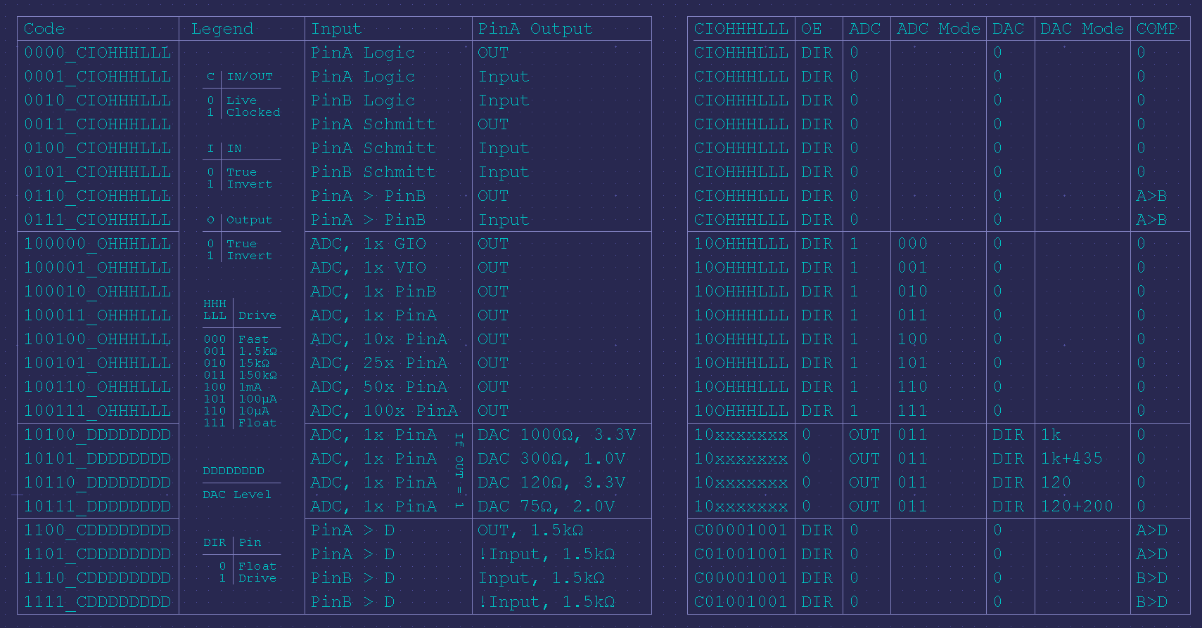
Here are the raw pin modes:
I'm thinking it would be good to make some shortcut/shorthand instructions for select cases of WRPIN, where an 8- or 9-bit immediate #D could get some quick business done.
I've thought of a few possibilities:
EEEE 1011110 1LI DDDDDDDDD SSSSSSSSS    SETPIN  {#}D,{#}S

	{#}D			WRPIN {#}D equivalent
	%000HHHLLL		%0000_0000_000_0000_000HHHLLL_00_00000_0		Logic in, digital out
	%001HHHLLL		%0000_0000_000_0011_000HHHLLL_00_00000_0		Schmitt in, digital out
	%010HHHLLL		%0000_0000_000_0110_000HHHLLL_00_00000_0		A>B in, digital out
	%0110DDDDD		%0000_0000_000_1100_0DDDDDDDD_00_00000_0		A>Level in, 1.5k out
	%01110xxxx		%0000_0000_000_0100_000101101_00_00000_0		Schmitt latch with 100uA hold
	%01111xxxx		%0000_0000_000_0111_001001001_00_00000_0		A follows B, 1.5k out
	%1HHHHLLLL		%0000_0000_000_101x0_HHHHLLLL_10_00000_0		Bit DAC output

EEEE 1011111 0LI DDDDDDDDD SSSSSSSSS    SETDAC  {#}D,{#}S

	{#}D			WRPIN {#}D equivalent
	%DDDDDDDD		%0000_0000_000_101x0_DDDDDDDD_00_00000_0		Set DAC output to D[7:0]
These modes could be lots of different things. Just have to narrow down the most-useful ones.
Here are the raw pin modes:
Comments
This would make it really easy to make a pin into a DAC output:
        SETDAC  dacval,#pin
        DIRH    #pin
Or, say you want to pick drive levels for a pin:
This saves the trouble of dealing with unwieldy ##D values or static longs located elsewhere in your code.
That's pretty cool.
Neat little feature.
Yes. Nice optimization
1. How many instructions is this saving?
2. How often is the this instruction typically going to be executed?
Playing the same role, this would use up both of the two empty D,S slots being kept for a rainy day. Are these two new instructions equally important? Could D[8] of SETDAC allow more modes in a single instruction?
So you are making a teensy ROM here that packs some common expansions into silicon ?
I can certainly see the appeal in reducing COG memory impact, but are there other ways to reduce such impact ?
eg
Can an init-table be placed in HUB, (or LUT) for example, and then a simple loop does all port inits ?
Or is is simpler to just have any such do-once init code in HUB, whilst the main code runs in COG.
Those are all tool-flow solutions, that do not need to consume any verilog silicon, and they are more flexible.
How is this going to impact the current silicon testing?
Having said this, I am finding a problem converting P1 code. The big "gotcha" is the missing equivalent JMPRET [D],[#]S instruction. The problem comes with self-modifying code, and the direct 9-bit jumps. There were other tricks done with the WC and WZ setting but these are rarer and can be overcome with additional instructions.
It would make a huge difference having a JMPRET instruction equivalent. What does it need?
It needs a bit for the NR case where the instruction is just a JMP or RET where no return address is being written. A bit for immediate #S (an "I" bit) is required. S is either an immediate goto address in cog, or a cog register storing a 9-bit cog address in its S bits.
For the JMPRET or CALL equivalent, the cog return address is written to the S bits in the cog register pointed to in the 9-bit D address.
Note this instruction only works in COG. Addresses are direct, not relative, because they can also be set using SETS and SETD (formerly MOVS and MOVD) instructions in self-modifying code.
Now, we can use the JMP {#}S direct 20-bit address instruction for the JMP and RET replacement. The SETS instruction works here too. The upper address bits just remain as 0's. BUT, there is the case where we use JMP S to jump to an address stored in the S-bits of the cog register pointed to by the S address. That S-register might have higher bits set (ie not 0's) and in that case, the JMP S direct 20-bit instruction doesn't work.
Next are the JMPRET and CALL equivalents which are really just a JMPRET D,{#}S where D is a 9-bit cog register where the 9-bit cog return address will be written into its S field, and {#}S is the 9-bit cog address to jump to. Optional WC and WZ bits would be nice but as I said can be worked around. They would be set as per P1, not P2. A shortcut can be use to just set Z and C. In P1, the WZ was used to set NZ as the only way Z could be set is if the code wrapped to cog $000 from the shadow register $1FF which is almost impossible. I cannot recall if WC was ever used and how it was set.
Thoughts please.
p2gcc always uses CALLD PA,#A. If you are running from cog memory you can use the first form. If the target address is in hub RAM, the return address will need to be in PA, PB, PTRA or PTRB.
I don't like the idea of it being a macro expansion if it results in more than one instruction result, that obfuscates things.
Good documentation with examples showing exact instructions needed for these common cases will go a long way.
setdac(dacval) and setpin(%HHHLLL) could be compiler pseudo-functions that return a long suitable for passing to wrpin. You could then do any of the following:
That looks like a good solution to me. No need for new instructions at all!
The only point is to make single-instruction common-use cases available for the assembly language programmer. Throwing in ## or dedicated static longs in registers is kind of messy if it can be cleaned up a bit.
This is something that can and should be done in software/documentation.
You could use your argument to add 100s of new instructions all over the place. I really wish you wouldn't.
We've got DACs that can be instantly used on every pin. It's a bit of a shame to not make it as easy as possible. Same with the pin-drive modes.
WRPIN, with that 32-bit word with all those bitfields, will stop everyone in their tracks. Nice to be able to get resistor or current drive with 'PINDRV #%HHHLLL,pin' or revert to normal with 'PINDRV #0,pin'. And to make a DAC output with 'PINDAC #value,pin' is so simple, too.
This would eat the empty instruction slots, but take few gates. I see it as a nice creature comfort for the programmer.
You are over worried about minor syntax differences I think.
These instructions save longs (## or register) and are way easier to remember.
For example, this (2 longs):
becomes (1 long):
For DAC setting, the savings is even greater.
This (3 longs):
        SETBYTE dacmode,dacvalue,#1
        WRPIN   dacmode,pin
...
dacmode LONG    %10110_00000000_00_00000_0
becomes (1 long):
If all you seek here is "nice creature comfort for the programmer" you can do that with some macros, and maybe some Config wizards, all external to P2 silicon.
The better vendor tools have graphical config tools, that show the result of the code, as in operating mode, critical init values etc,
Some even have simulators that do the same thing, but live at code-step, so you can watch the before.after config and see the modes change.
The only silicon reason I could see for this would be to save bytes of code space, but that does not seem to be a focus here ?
I have found it a bit clunky having to fiddle with building a config long and then going throught the smart pin write as an additional step.
This scheme seems way more logical to deal with the DAC direct and remove the "moddle" man.
My 2 cents...
So, I worked out the constant sections first, then applied them to combine into a new constant. Turned out to be quite simple really.
See my sample clock setting code in the P2 Tricks and Traps thread.
Nothing special required here. No changes to the silicon or the compiler.
IMHO, setting the pin values for pull-ups/pulldowns will typically only be done once. Seems a shame to waste silicon for this.
For your first example, could become
For your second case, if you made setq before wrpin replace byte 1 of the wrpin with its own argument:
SETBYTE dacmode,dacvalue,#1 WRPIN dacmode,pin ... dacmode LONG %10110_00000000_00_00000_0could becomeSETQ dacvalue WRPIN ##pindac(0-0),pin ' 0-0 replaced with setq valueYou could also use setq with pindrv(0-0):
        SETQ    #%HHHLLL
        WRPIN   ##pindrv(0-0), pin
EDIT: setpin -> pindrv
In contrast, SETDAC/PINDAC looks to be useful and could be more so. I'd call it WRDAC and here are a couple of options for enhanced capability:
Option 1 - single pin
Option 2 - single/multiple pins