

Fried another Propeller! Please help!
 henryclever
Posts: 15
henryclever
Posts: 15
Hello, I am looking for some help in getting my system up and working and I'm kind of stuck at the moment.
I have fried my second propeller since ordering more! Kind of frustrated.
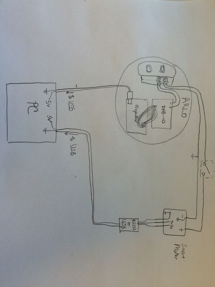
I attached a picture of how I connected my Arlo bot. I have another motor being powered off of my Arlo base—this motor is controlled from my computer through an RS232 signal. When I do NOT have this motor connected, the base drives just fine. When I have the Propeller disconnected, the other motor works just fine. However, If I hook up both of them (as shown in schematic) and turn on the switch to power the other motor, it fries my Propeller! At least, the USB power input no longer works but the Aux power input will turn it on. Either way, I can no longer upload code to it.
My suspicion is that because the RS-232 from the motor operates on a +/-10V potential, it alters the ground potential and sends a small surge of power through the servo pins, frying the Propeller.
On the first propeller I fried, I thought the issue was something else so I checked all my connections and redid it as shown in the diagram, but the result was not good. Can you help me with this? I feel like I have done everything that I should have done, and now I’m out an $80 board and not sure where to proceed.
Thank you,
Henry C.
I have fried my second propeller since ordering more! Kind of frustrated.
I attached a picture of how I connected my Arlo bot. I have another motor being powered off of my Arlo base—this motor is controlled from my computer through an RS232 signal. When I do NOT have this motor connected, the base drives just fine. When I have the Propeller disconnected, the other motor works just fine. However, If I hook up both of them (as shown in schematic) and turn on the switch to power the other motor, it fries my Propeller! At least, the USB power input no longer works but the Aux power input will turn it on. Either way, I can no longer upload code to it.
My suspicion is that because the RS-232 from the motor operates on a +/-10V potential, it alters the ground potential and sends a small surge of power through the servo pins, frying the Propeller.
On the first propeller I fried, I thought the issue was something else so I checked all my connections and redid it as shown in the diagram, but the result was not good. Can you help me with this? I feel like I have done everything that I should have done, and now I’m out an $80 board and not sure where to proceed.
Thank you,
Henry C.
Comments
Thank you!
-H
Mike,
I'm just connecting the Propeller to the DHB-10 motor control board in the way that Parallax instructs in the Arlo manual. The Propeller uses P12 and P13 servo pins to run each side of the DHB-10. It works fine this way without the extra motor hooked up. Here is a link the the instructions:
http://learn.parallax.com/tutorials/robot/arlo/arlo-robot-assembly-guide/section-7-control-components-and-dhb-10-connections-2
Beyond that, I'm not sure.
Thanks,
-H
I recently killed an Activity Board by powering it from a battery and USB at the same time.
What are the connections between the DHB-10 board and other Propeller board?
There may be a ground connection missing somewhere
I'm only frying the Propeller. The USB->RS232 connector is fine.
I'm not using any other boards except another Dynamixel2USB connector for a Dynamixel motor communicating via RS485. I left this out because it has no effect on either and always works regardless. The system as a whole is running on a PC with ROS (publisher/subscriber architecture) using ChrisL8's propeller and Linux ROS software listed here: https://github.com/chrisl8/ArloBot
The Smart Motor is an Animatics Servo, an SM2315DT-BRK. It actually runs on 24 V--the switch also has another 12V battery connected in series with it. I left that out of the schematic, but if we really need it, I'll redraw the schematic with this included.
I do suspect a grounding issue, I just haven't cracked it yet. If the DHB-10 and the Propeller are disconnected from each other but everything else is turned "ON" except the Smart Motor, then the ground difference between the computer (and Propeller) and the DHB-10 (ground is same as batteries, Smart Motor, and Dynamixel) is 2.6 volts. However, when I turn "on" the motor, this ground changes from 2.6 to 0 V. If a wire is just connected directly from the computer USB to the batteries (independent of the Propeller), then it balances the ground in both locations so it goes from 0.004 V to 0.000 V on my multimeter when the Smart Motor is turned on, which I think is negligible.
I believe this 2.6 V is due to something in the USB/RS232 connector, because it essentially steps the RS232 TX/RX signal down from 10V (well 9.78 to be exact) to the normal USB voltage of 5.
Warmth,
Henry C.
The RS232/USB connector is by the bottom wheel. The switch that says operate is what turns on the motor.
I have checked and rechecked my voltages, and everything seems to be what I would expect. The ground of the Smart motor is the same as all the others, as the extra battery (-) side is connected to the (+) side of the other batteries, so it is the only part that has 24V.
Any tips for solving this presumably ground loop issue?
-H
-H
Not sure what you mean here. I expect the ground of my DHB-10 input power to be the same as all my other grounds, which it is.
-H
Your photo gives the answer as I can see you only have the wheel motors at the terminals. So that is all good.
Can you illustrate how the 2 batteries are wired?
Just can't quite make that detail out in the photo, so that might be something!
The diagram above was a simplified version of my circuit. Here is the in-depth one. It is wires so if the switch is down, then all the batteries are in parallel so they can charge together. If the switch is up, disconnects B3 from the parallel circuit and puts it into series. I have confirmed that all the voltages are are what I think they should be.
The voltage select headers are definitely set to 5v.
After thinking through this again, I suspect the 'pole 1' in the circuit might have something to do with it, because in 'charge' mode the motor is entirely disconnected. Is it possible that the "surge" would go away if I just hardwired the motor ground to the other ground so that pole 1 would just be always shorted?
Thanks,
Henry C.
H
The input to the dhb10 is your system +ve and gnd, so those wires would go to your 12v power source, perhaps via your switch or the arlo pdb switches.
If you had either of the motor cables hooking into your common ground, then stuff will go bang!
The same could be true of the smart motor gadget you have, so it might be worth checking your connections at that device. Especially if your mixing 12 and 24v. Chris mentioned groundloops already. Can you run all the motors on 12v? at least for simplification/troubleshooting.
Sorry if this reiterates something youve got right already, but system gnd joing one of the motor (output) terminals would be a candidate for your issue.
They are connected directly to the wheel motors. The system drives and works fine (without the Smart motor)
The input to the dhb-10 is connected to +12v and ground. See the black and yellow wires in the previous picture I posted.
Smart motor definitely has +24V. I cannot run it on 12V.
Henry
I'd suggest you think through the cabling again, and if I dont see any other help or eureka moments posted here, then I'l be able to print your wiremap to take a proper look in the morning.
Btw... the overall build looks really neat and tidy! Like it!
Hi VonSzarvas,
Thank you for the compliment, and the continued help/interest!
The ground to the Smart Motor is switched by "pole 1" on the triple pole switch. Do you think that this is what is causing the problem? That perhaps instead of the current design, I should just always have the ground of the Smart Motor connected? More details on the voltage issues and the partnumber (it is an Animatics SM2315DT-BRK) for the Smart Motor listed in my previous posted at 12:16 PM.
I will be working on this from 12-6 EST tomorrow afternoon - I need to have it fixed ASAP (other people are counting on me
Here are my two next steps, if anyone in the loop, please feel free to suggest something else:
1. Add 100 ohm resistors to all wires between the Propeller and the DHB-10 to protect the servo pins (P12 and P13) from the suspected surge that is going on - remember, it doesn't fry if these aren't connected.
2. Hardwire the ground of the Smart Motor to other grounds so even if the motor is turned off (by toggling the 24V and the series/parallel switchup), the ground is always connected.
Other suggestions to protect my last Propeller? It is no fun to debug things when the nearest limiting factor is to blow up an $80 part or not.
Thank you for your help!
Henry C.
I took a look at the schematic you posted and was having a bit of a hard time following the connections so I redrew with the correction you posted.
Please verify that by "AH I messed up a bit on the schematic above. The motor's (-) connection is actually on the top of that switch pole, not the bottom of it" you mean the - connection of the smart motor should go to the top of pole1 of the switch. That makes more sense than having it on the bottom.
I see that the negative connection of the smart motor goes to the negative output of the 5A motor out connection. I would have thought that it would go to the negative connection of battery B2 so that the smart motor would receive 24V when batteries B2 and B3 were switched from parallel to series.
kwinn seems to have figured a solution
As you said in your 2nd idea above, just be sure you are not cutting the ground path between the DHB10, AB and the battery. Keep them always connected and only switch the +12V into the DHB10 and the +24V into the Smart Motor.
At the moment (when powered by USB), your AB relies on the DHB10 for local ground. If you are switching off that ground supply, then your ground path suddenly becomes a big unknown loop, sinking up the USB cable to the PC.
If you are not planning on powering the AB from the PDB in the future, then adding a jumper from the AB ground to the PDB ground might be considered for extra protection if a crucial cable becomes unexpectedly disconnected.
Incidently, that smart motor datasheet shows 5V TTL I/O control pins. Have you considered dropping the pc-usb-rs232 cable, and instead run the smart-motor off the AB directly? A couple of the AB servo headers have built-in series 3.9K resistors, so they are compatible with 5V TTL. Or add your own series resistor to a spare propeller I/O. If doing that, going with 10K-100K series would provide tougher protection.
Hope you figure this out today!
Hi kwinn,
First, thanks for investing your time in this. Yes, you correctly interpreted my comment. The negative connection is connected to the negative side of the 5 A output which is just the same as the (-) side of battery B2. All the negative sides of the connectors on that power board are connected to a common ground.
Instead of that red wire from pole 3 going directly to the connection of battery 2, I have it wired to the + size of the 5 amp output to keep my Smart Motor Fused. So yeah, it's basically the same as your second diagram, so as far as I see, nothing should be changed on that end except possibly suggestions (1) and (2) I listed previously.
Henry
At the moment (when powered by USB), your AB relies on the DHB10 for local ground. If you are switching off that ground supply, then your ground path suddenly becomes a big unknown loop, sinking up the USB cable to the PC.
By this ground supply, do you mean the ground of the smart motor or a different one? Just want to be sure I know what you mean.
What is the PDB?
Sounds like a good idea, however, I only have a software driver for the RS-232 side. While I'm sure this is possible, I'd rather just add a ground in the loop or a couple resistors-I am better at hardware.
Thanks!
H
Stands for "Propeller Development Board".
I think the reference was to the Power Distribution Board:
https://www.parallax.com/product/28996
The Propeller Development Board is usually referred to as PPBD, (Propellor Professional Development Board).
EDIT: The BS2 Development Board was referred to as PDB, so I see where the reference was.
Sorry, what does the "P" stand for?
Personal maybe.