

Encoder Idea
 Elaine
Posts: 8
Elaine
Posts: 8
I finally got a replacement for my Bourns 64-pulse per revolution optical encoder and have been playing with it all day. I can read left and right rotations reasonably well using the attached look-up table.
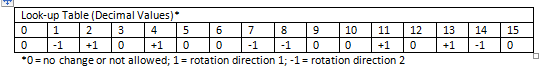
The problem is that the zeros mean different things. The first 0 (offset =0) means no change in position. The other 0's are effectively errors, such as skipped reads. The characteristic of which is more than one bit changes in the binary value I am reading. In brief, the +1's and -1's are added to an accumulator to determine the actual number of "clicks."
Since "true" zero should be much more common than the other zeros, I am thinking of using another value for the other zeros, such as "2" that could be easily tested for (e.g., xorlw 0x02, skpnz). Any other ideas?
Thanks, Elaine
Comments
It is a strange way to present optical encoder info.
Usually, for any given counter value, there are 4 possible paths +0 (no change), then +1 or -1 and finally Err, which is both Quad channel changed, and that can go to another decision tree.
Some systems treat that as a speed overrun, and use the previous delta, others flag it as an error.
Agreed.
I'm guessing this is a quadrature encoder.
Quadrature output has two pins which transition between high and low with only one channel changing at a time.
The channels are often called A and B.
In one direction you'll get output like this.
0, 0
0, 1
1, 1
1, 0
and then back to 0, 0.
In the other direction you'll get the following output.
0, 0
1, 0
1, 1
0, 1
The program can tell which direction the encoder is rotating to keeping track of the previous output and checking it against the new output.
If the previous output had been 1, 0 and the new output is 1, 1, then we know the encoder is rotating according to the first set of outputs listed above.
I posted some quadrature encoder code here.
If the code has been written correctly, you can't "fool" the encoder by rotating it back and forth a small amount. As mentioned in the thread linked above, there's an object in the OBEX which doesn't count transitions correctly.
I'm pretty sure there's some quadrature encoder code in the Propeller Tool's library.
This method doesn't require that the inputs be contiguous and allows for CHI (index) handling (typically in "A0B0:" below).
It's in PropBASIC (therefore self documented) which translates directly to PASM.
DEVICE P8X32A, XTAL1, PLL16X FREQ 80_000_000 Chan_A PIN 6 INPUT Chan_B PIN 7 INPUT Chan_Z PIN 2 INPUT Counter VAR LONG = 0 HubCTR HUB LONG LoopCTR VAR LONG = 0 Idx_Monitor VAR LONG = 0 Idx_Count VAR LONG = 0 Count_Error VAR LONG = 0 PROGRAM Start Start: Watch Counter ' This is for ViewPort 'Decide where to start If Chan_A = 1 And Chan_B = 1 Then Goto A1B1 Endif If Chan_A = 0 And Chan_B = 0 Then Goto A0B0 Endif If Chan_A = 1 And Chan_B = 0 Then Goto A1B0 Endif If Chan_A = 0 And Chan_B = 1 Then Goto A0B1 Endif 'Keep hopping between these labels A1B1: If Chan_A = 0 Then Dec Counter Wrlong HubCTR,Counter Goto A0B1 Elseif Chan_B = 0 Then Inc Counter Wrlong HubCTR,Counter Goto A1B0 Endif Goto A1B1 A0B0: If Chan_A = 1 Then Dec Counter Wrlong HubCTR,Counter Goto A1B0 Elseif Chan_B = 1 Then Inc Counter Wrlong HubCTR,Counter Goto A0B1 Endif Goto A0B0 A1B0: If Chan_A = 0 Then Inc Counter Wrlong HubCTR,Counter Goto A0B0 Elseif Chan_B = 1 Then Dec Counter Wrlong HubCTR,Counter Goto A1B1 Endif Goto A1B0 A0B1: If Chan_A = 1 Then Inc Counter Wrlong HubCTR,Counter Goto A1B1 Elseif Chan_B = 0 Then Dec Counter Wrlong HubCTR,Counter Goto A0B0 Endif Goto A0B1 EndThe cool thing about such a table is that it can be completely represented in the Prop as one 32-bit long.
-Phil
-Phil
and the P2 is supposed to have 16 of them.
Enjoy!
Mike
Of course that has other complications...
Yes, that was a fairly large oversight.
- but U/D counters are slightly slower than single direction counters.
What part did you choose ?
No kidding.
I'm glad you asked because I forgot to thank you for finding it for me, several years ago :-D
I have sixteen of THESE on order.
I might just grab a BiSS-C master device to play with. More and more demand for absolute encoders out there.
I've only dealt with relatively slow encoders.
I don't suppose you have a source a motor encoder combo which would tax the Prop the way you describe?
Thanks for the links to the encoder chips. I'll probably get a couple to try.
Well the complete kit involves the servo drive also. This is the Emerson/Control Techniques Unidrive range that I am mainly working with. The nominally rated 6,000 RPM servo motor is momentarily pushed to a higher RPM and it is equipped with a 4096 line encoder (16,384 quad counts/rev).
I see the LSI-LS7082N is a rather old looking 10V CMOS device spec's down to 4.5v, and at that 4.5v spec is ~ 4.75MHz Max
The LSI-LS7366R specs 20MHz clk at 3v3
The LSI-LS7082N function of Quad pins to CkUP and CkDN, you can fit into a SPLD,
and I think doable is
a Pair of Quad->UP/DN clocks in an ATF16V8BQL
and 5 pairs in ATF750xx, and 7 or 8 pairs in ATF1502
Not sure of the MHz, but 20MHz or 40MHz state clock should be possible.
Oh 4.75MHz will have me well covered. For SPI type devices, I have ordered one of THESE to play with.
You're whetting my appetite again, dammit.