

Mood Enhancing LEDs
 Duane Degn
Posts: 10,588
Duane Degn
Posts: 10,588
Edit: (5/17/13) I'm marking this thread "Completed" since I've delivered it to my niece. There are still many things I plan to change about this project. The radio and real time clock are not presently used in the software though the hardware for these components are installed. I plan to get the clock and radio working sometime in the future.
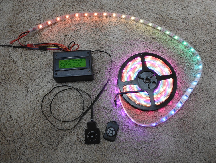
Here's a project I've been working on lately. They are LEDs to help make a hospital room a bit cheerier. My niece is pregnant and due in about three weeks. Three weeks ago at her regular doctor's visit the doctor had her check into the hospital instead of having her return home. There is some sort of complication requiring my niece to stay in bed (and hospitalized apparently) the remainder of the pregnancy.
My niece had expressed her fondness for LEDs after seeing some of my earlier LED projects so I decided to try to add a user interface to my strand of 160 WS2801 controlled LEDs.
I have a five button wearable keypad I purchased a while ago from SparkFun. I thought it would make a good interface to the LEDs.
Have you all ever noticed making a user interface can be a challenge? Man, it was a lot harder than I thought to get the interface to work the way I had imagined. Button debouncing and detecting long presses to speed up the rate of change takes a bit of thought.
I'm still not satisfied with the way the UI is working. Since there are so many possible screens to scroll though, I may break out the screens into sub menus.
While I like the wearable keypad, I kind of wanted a wireless controller. Fortunately I have several Nordic fobs. Another retired SparkFun product. It also has five buttons so I could keep have the two devices control the LEDs in a manner similar to each other. The fob has its own set of debouncing issues but it seems to be working okay. Thanks Ron Czapala for figuring out which bits go with which buttons on the Nordic fob
The deadline for this project is Tuesday. I intend to install the LEDs in my nieces' hospital room on our Tuesday visit. I'll still have changes to the software but I won't have hardware of my own to test it on.
I made a video showing the LEDs but the sound quality was really bad (I really dislike our Fujifilm XP waterproof camera). I'll make another video and post it soon.
(Here's the unlisted really boring really poor quality video. Don't watch it. Wait of a better video.)
I plan to make another video this evening (when it's dark) with the LEDs stretched out to their full length. This video here give you an idea of how long the strand it.
I'm using JonnyMac's WS2801 object again. I also used his object to control LEDs on my hexacopter.
I forgot to take pictures of the electronic before closing up the enclosure. I'm using a QuickStart board as the brains. I've added a partial bill of materials below. I think the only things missing from the BOM are some connectors.
Edit(3/4/20): Fixed some links.
Comments
QuickStart Board (Link Fixed 3/4/20)
FM Radio Receiver Module (No longer available at Parallax.)
Serial LCD (4x20) (Link to similar LCD added 3/4/20)
DS1307 Real Time Clock
Wearable Keypad (retired)
Nordic Fob (retired)
MCP3002 ADC (not yet used, I may add a light sensitive resistor to detect light levels in room)
Nordic nRF24L01+ Module (Don't pay more than $3 for one.)
Enclosure
Various Connectors (headers, Dean's connectors and headphone jacks)
I'm powering the LEDs with a 5V 3A wall wart. The LEDs appear to draw up to 2.5A.
Edited(3/4/20): Fixed links.
Version 130507a uploaded May 17, 2013.
Edit(3/11/15): Warning, the code attached is an old version. There are likely better options available.
I plan to upload this program or an improved version to my GitHub account
If there isn't code similar to what is attached here on my on GitHub, send me a message and I'll make and check for any improved versions of the code.
Retired SparkFun Wireless products
I don't see it the same way. I think a lot of the retired products are just older versions of what they are selling now. They still have a lot of wireless devices, they are just spread across several subcategories. I was disappointed to see the Nordic fob retired. I really like those things. The enclosure is still available from Polycase, I may try to make my own PBC to go into the enclosure.
The key fob was a nice unit.
I was just wondering what the Hospital might think about your RF signals beaming about the room?
I don't see the harm, but maybe the Hospital has machines that don't respond well to these signals?
I'm sure there won't be a problem, but it might not be a bad idea to ask the staff...
-Tommy
Thanks Tommy! I can't believe am disappointed I hadn't thought of this.
The Nordic transceiver in the black enclosure doesn't transmit. The standard firmware in the fob is transmit only. There isn't two way communication between the devices so if the fob isn't used, there shouldn't be any RF signals produced.
I'll check with the staff as you suggest and if there's a problem we won't use the wireless fob.
It occurred to me yesterday that it may be a good idea to have some space between the black control box and the start of the LEDs. I asked about how to wire the extension in this thread.
I received a bunch of helpful answers. I was fortunate to have Tracy Allen check in on the forum to lend his advice.
I later realized I wasn't sure if these LEDs qualify as I2C devices. There is no return data coming from the WS2801 so the lines can be actively driving. From what I've learned here on the forum (I think from Phil), and actively driven signal can be much faster than one relying on pull-up resistors. JonnyMac's driver doesn't require pull-up resistors.
BTW, I'm not using any logic level translators in any of my WS2801 projects. The 3.3V logic seems to work fine.
I was also glad to get Tony's and Andrew's input about the wiring.
xanadu pointed out that twisted pair is particularly important in differential signals and added this encouragement.
Thanks for the kind words.
I had planned to take some pictures and video of the LEDs up in the room but I apparently left my SD card at home. It must be somewhere on my desk in front of me but I can not see it yet (if you saw my desk, you'd understand why I couldn't immediately find a SD card on it). My wife will be up to visit her on Tuesday (she visits on Tuesday and Thursday evenings) and I'll ask her to take some pictures and video of the lights (as she chats with our niece (and helps our niece with crocheting a baby blanket(my wife has a black belt in crocheting))).
My niece and her husband live about 90 minutes away from where we live. The hospital in a largish city between our two towns. It takes about 55 minutes to drive up to the hospital from where we live. This traveling time is what limits the visits to two a week (her husband stays with her on the weekends).
So video and photos of the LEDs in action will need to wait for a few days.
I had planned to take the LEDs up on Tuesday but was sick. My illness gave me a chance to clean up the menu selection quite a bit. I thought the menus were more logically laid out in the version I took last night than the version I had intended to take on Tuesday.
The couple of day delay let me add a Larsen scanner. JonnyMac's demo code included a Larsen scanner but I wanted to add a few features. Since the LED strip is 160 LEDs long, I thought it would be good if the strip could be broken into several different zones for scanner to operate. I also wanted to add a way of spreading the "dot" over several LEDs. The spread amount could be changed.
This brings me to something I've noticed with LED brightness before. It would appear we register brightness, a lot like loudness, in some sort of logarithmic scale. I originally used a linear dimming algorithm to transition from the center bright LED out to the dimmer ones but found the LEDs didn't look like they dimmed much until well away from the center. I then tried a halving the brightness with each LED from the center and this gave a much better look. Halving the brightness of an 8-bit brightness value can only go on so long so my logarithmic decay was only used when the Larsen scan was only stretch 7 LEDs of less. For larger stretches, I used a linear brightness decay.
I have a few methods I think may add to JonnyMac's already very useful code. I'll share them in a subsequent post.
But no playing favorites, just 'cuz she's family. I'm under the weather myself. Still have some kind of flu, and I'm almost over a bout of Pinkeye. Maybe you can whip something up to make me feel better! Xbee, Zigbee, Blackfin, touchpad, HiFi, WiFi, 4GLTE, I2C, whatever you like.
I leave for China in a week. Chances are, my health be back at 100% just as I board the plane, only to catch something new on the plane or in Shenzhen, in spite of all the shots & pills I've recently gotten for Hep A. Hep B, Polio & Typhoid. On the plus side, maybe I can meet some of my favorite Ebay sellers face to face on this trip.
Best wishes to your niece and family. A most exciting time! Change a diaper early. It's good for the soul!
I'm sure "Duane" was at the top of their "If it's a boy" list, but alas future baby appears to be a girl. The planned name is Sonja.
Sorry to hear you've been sick. Here are some LEDs to help your mood.
I'm considering bringing these LEDs up to the hospital as well. The controller box has a connector on the back so the hardware aspect of adding these LEDs is already done. I'll need to figure out how to modify the menu system to include controlling these LEDs. I may want to change the text it displays as well.
Wow! China! How exciting. Business or pleasure?
As a young adult, my father spent a few years in Taiwan and Hong Kong. He caught Hep A. Apparently it's not a fun illness (like pinkeye is).
Thanks. Even though we don't have children, having nine younger siblings has allowed me to change more diapers than most parents.
Hope you're feeling better soon.
Will be in Shenzhen for 2 weeks for work. Should be interesting. Not sure if I'll have general internet (ie Forum) access or not. Do good things, whether you hear from me or not!
This sounds very interesting. I hope you tell us about your travels on your return (or sooner if you have a chance).
This is the method I used to make these transitions.
PUB MergeColors(initialColor, finalColor, distinationPtr, localSize) | tempColor[3], {
    } colorMultiplier, localIndex, initialColors[3], finalColors[3], pseudoIncrements[3]
'' localSize should include the initialColor but not finalColor.
  repeat until not lockset(debugLock)
  Pst.Str(string(ASCII_CR, "MergeColors Method ******"))
  Pst.Str(string(ASCII_CR, "initialColor = "))
  Hex(initialColor)
  Pst.Str(string(ASCII_CR, "finalColor = "))
  Hex(finalColor)

  BustColors(initialColor, @initialColors)
  BustColors(finalColor, @finalColors)

  ' find incremental color change
  ' use the "1000" mulitplier to reduce rounding errors
  ' Note we divide by multiplier prior to assigning color
  ' to expanded pattern buffer.
  repeat result from 0 to 2
    pseudoIncrements[result] := ((finalColors[result] - initialColors[result])* 1000) / localSize
    Pst.Str(string(ASCII_CR, "pseudoIncrements["))
    Pst.Dec(result)
    Pst.Str(string("] = "))
    Pst.Dec(pseudoIncrements[result])

  colorMultiplier := 1

  ' assign initial color
  long[distinationPtr] := initialColor

  ' assign between colors
  ' final color not copied here. It will be copied as the
  ' initial color of the next loop
  repeat localSize - 1
    distinationPtr += 4
    repeat result from 0 to 2
      tempColor[result] := initialColors[result] + (pseudoIncrements[result] * {
                         } colorMultiplier) / 1000
    ' assign altered color
    long[distinationPtr] := Leds.make_rgb(tempColor[0], tempColor[1], tempColor[2])
    Pst.Str(string(ASCII_CR, "long["))
    Pst.Dec(distinationPtr)
    Pst.Str(string("] = "))
    Hex(long[distinationPtr])
    colorMultiplier++
  lockclr(debugLock)
For example, if I wanted to fill a few buffer positions with transition LEDs between the colors red on orange, I'd set "initialColor" to red ($00_FF_00_00)
and "finalColor" to orange($00_FF_1F_00). The variable "distinationPtr" is the location in memory to store the resulting colors. The variable "localSize" is the number of transition LEDs to use between the two colors.
Here's what the debug output looks like when transitioning from red to orange over 24 LEDs.
One of the first steps to merging the colors is to break the colors apart to their red, green and blue components. I use the "BustColor" method to find the component colors of both the initial color and the final color.
I use the components of the two colors to come up with a value to incrementally change the initial component value to the final component value (a kind of slope to the line). I use a multiplier ("1000" in this case) to reduce rounding errors.
repeat result from 0 to 2    pseudoIncrements[result] := ((finalColors[result] - initialColors[result])* 1000) / localSize
    Pst.Str(string(ASCII_CR, "pseudoIncrements["))
    Pst.Dec(result)
    Pst.Str(string("] = "))
    Pst.Dec(pseudoIncrements[result])
You can see in my red to orange example the only component to change is the green component.
To transition from red to orange over 24 LEDs (25 total steps) the green component of the color should change 1.192 units with each step. Of course we're using integer math so I used the "1000" multiplier to make 1.192, 1,192. This incremental change gets added 24 times (the final 25 step isn't added since there is already an orange LED).
Each of the steps can be thought of as "x" in a linear equation:
y = mx + b
"y" is the value for the transitional color's component color, m (the slope) is the "pseudoIncrements" value for that particular component and "b" is the initial color's value. Since the value "m" had been multiplied by 1000 I divide the "m * x" portion of the equation by 1000 prior to adding "b".
I've seen this technique of using a multiplier (1000 in this case) referred to as "pseudo real numbers" in some of the Parallax literature. It's a very useful technique and IMO easier than switching to floating point numbers and back to integers.
I thought it ironic that after going through the trouble of stretching the rainbow with my MergeColor method, my niece said (as I was showing her how to control the size of the rainbow and scroll speed) "Oh, what's that setting, that's my favorite.) It was the rainbow without any expansion at all. The really easy effect is what she liked the best.
Before the buffer holding the various colors to be displayed was feed to the WS2801 driver, I modified all the colors in the buffer to adjust the overall brightness.
I'm attaching the present version of the code (bugs and all) to post #4.
I think I may switch this to "Completed" since it is currently in use.
I don't see the LEDs on your bom?
Jim
Jim,
I purchased the LEDs off ebay. They are no long available from the same seller.
You should be able to use any strip using WS2801 as controllers.
Here's a 1m strand sold by SparkFun($44.95). Here's a strand of 5m on ebay (dead link removed). $83.55 seems like a pretty good price for 5m.
My LEDs came with a weather proof cover like the ones at NooElec. The NooElec 5m strand costs $144.95. I've purchased stuff from NooElec before and I think they're a good seller.
If you (or anyone else) is actually thinking of using my code, let me know and I'll try to clean it up a bit more. I know there's a serious bug in the menu selection in the version I posted.
Edit(3/4/20): These prices are way out of date. I no longer think the NooElec strand is a good deal.
I may need to delay my offer to clean up the code. Since I don't have the hardware here, I'm afraid to make any changes.
I'd think most projects would benefit more from JonnyMac's original demo code. There may be a few methods from my code that could be useful in other projects.
I kind of like my "LoadLarsen" method since it sets up several scanners within the a strip. 160 LEDs is kind of a lot to watch a LED blip scan back and forth. The number of simultaneous scanners is adjustable in my code (I think it's kind of cool). The number of LEDs turned on in the scan is also adjustable.
The constant "CHANNELS" should be changed to however many LEDs are in the strand. Several buffer sizes are dependent on the number of "CHANNELS" in use.
I never did get an updated video of the LEDs in action. My niece had her baby about four days after I delivered the LEDs. I thought the baby was just two weeks premature but the "due" date had been moved up by two weeks because of the complications my niece was experiencing. "Sonja" came four weeks early. My wife and I have visited Sonja and she sure looks healthy for being four weeks early. Both mother are baby appear to be doing well. Sonja will need stay in the hospital for a while. My niece was able to return home a few days after the birth.
My niece talked me into letting her take the LEDs home with her for a while. I don't know how long "a while" will be. I'm betting it will be whatever my niece decides "a while" means.
If anyone has questions about my code, I'd be glad to attempt to decipher it. I'm afraid there are lots of dead ends in the code since I had planned to use the radio and RTC but didn't get the code to work properly.
Jim
Pretty cool IMO.
I have the LEDs back from my niece but I don't currently have a decent video camera. I'll add a better video once I have a working camera.
Edit(3/4/20): Fixed image link.
A must-build for me. I have plenty of low-current red LEDs and the laser-cut background holder. Just tons of soldering to do!
Yes, that's cool and "mood-enhancing".
What is your "laser-cut background holder"?
Darn it! Why to you always do this to me? Now my head it swimming with possible circular LED layouts. I already have too many projects!
Wouldn't it be cool if instead of just being able to control the LEDs in rings, they could be controlled individually? Then one could have spokes and petals. Dang nabit! I don't need another project!
While I haven't yet done a circular LED project, I have made a hexagonal (sort of) LED layout.
Whatever you do, don't even think of making that circular PWM LED bloom. I forbid it!
My buddy laser cut some acrylic holders (backgrounds) for 5mm LEDs already to build these. Both black and mirrored. Just have to push the LEDs in and wire them up!
I've been working with the WS2812 LEDs (picked up some NeoPixels from Adafruit) and in their demo code there is a neat little routine called wheel that helps with creating rainbow effects. Here's the translation to Spin:
pub wheel(pos)

'' Creates color from 0 to 255 position input
'' -- colors transition r-g-b back to r

  if (pos < 85)
    return strip.color(255-pos*3, pos*3, 0)
  elseif (pos < 170)
    pos -= 85
    return strip.color(0, 255-pos*3, pos*3)
  else
    pos -= 170
    return strip.color(pos*3, 0, 255-pos*3)
This takes a value from 0 to 255 and transitions from red to green to blue and then back to red. By offsetting the value of pos in the LED string the rainbow effect is created. The color method simply packs the rgb bytes into a long.
I do like your mx+b approach, though, and will play with it.
Those NeoPixels are pretty cool. I'm sure there are lots of applications where one wouldn't want a the big black WS2801 chip on a PCB. I haven't looked at the protocol but I wonder if it's similar (or the same) as the GE35 Christmas lights like those in post #13 of this thread.
The "wheel" method looks like it's likely faster than my MergeColors method. It's certainly easier to read.
When attempting to make a Larson scanner with a decaying trail, I initially used the MergeColor method with whichever color I wanted to scanner to display and black (off). It turns out a linear decay doesn't look very good. I ended up decreasing the brightness by half for each step of the decay. I'm guessing we perceive brightness in a similar fashion to perceiving sounds, in a logarithmic scale (I should look this up, it would be a good thing to know).
Thanks for posting the "wheel" method and thanks again for writing (and sharing) the WS2801 driver.