

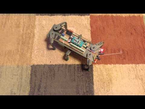
Stamp Bug 2 type "bot" - 3 servo, hex crawler

The original idea was to duplicate the "StampBug", Manufactured by Milford Instruments; England.
("One of those time's putting off ordering one, until, now it is
no longer available.") Now I have the "bug" for one.
I ordered the "Boe-Bot" with the, "crawler kit", as an intro to "walking bots".
What a fun bot, what a great experience assembling and learning
the program routines to make it go! (More on that later in another post.)
The Boe-Bot's infared navigation system worked very nicely,
so I used it in my "StampBug2" type "bot".
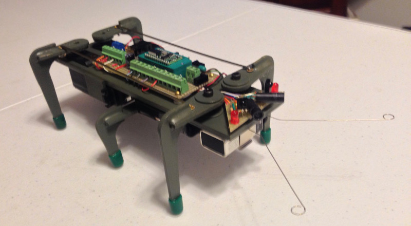
The antenna feelers are not currently wired, just on for looks. The original "bug"
used tactile navigation through the "antenna feelers". (so much for keeping it OEM).
Applying what I learned building the "Boe-Bot",
most of the program routines are from the, "Robtics with the Boe-Bot" manual, version 3.0 by Andy Lindsay.
Copyriight by Parallax Inc. Some of the sensors and electronic components used
are from the "Boe-Bot" Kit from Parallax Inc.
It was a big help for the start of this project to review pictures of the "StampBug2"
and the bug's original Basic Stamp program. Kudos to the user's of this forum for those posts.
Of course, it is those same post's that reminded me that I wanted to "play" with one some time ago.
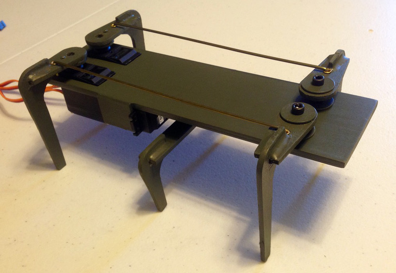
The body and legs were cut from hobby wood (bass) obtained from a local art store.
The legs were cut to include the OEM interlocking horizontal to vertical joints.
I don't have a pattern for them to include with the post, I drew them directly on the wood
itself (should have traced them out first, before I glued them together). The bolts, nuts, spacers,
and washers were obtained at our local hardware store.
The body was painted a olive green color.
The original program (and robot), "BUG.BAS" was based on the 8 bit Basic Stamp,
and used touch "feelers" to navigate. The program was efficiently
written to use the limited memory of the Basic Stamp.
I used the Basic Stamp 2, with more memory and
variables, the walking routines are written out
in sub-routines, making them easy to follow.
The original program actuated all three servo's at once for a nice smooth walk!
It seems the generic servos I used may be current hungry?
When operating the three servos at the same time,
it draws the voltage down on the batteries causing the servos to work erratically?.
Same for the Basic Stamp2, so I added the separate 9 volt transistor battery for the BS2,
and actuate only two servo's at a time. (The fix worked.)
As a result, the walking routines move the left and right legs separately, which slows the bot's walk.
(I really wanted to actuate all three servo's - for fluid operation.)
The center leg servo works the hardest and must be continually actuated to keep the right or left
side from drooping back down. I may try different servo's in the future.
The "bot" also seems to "crab" a bit, on hard surfaces, one direction, and on the rug, the other direction,
with no change in the servo parameters. Maybe better gripping feet, or shorten the stride may help?
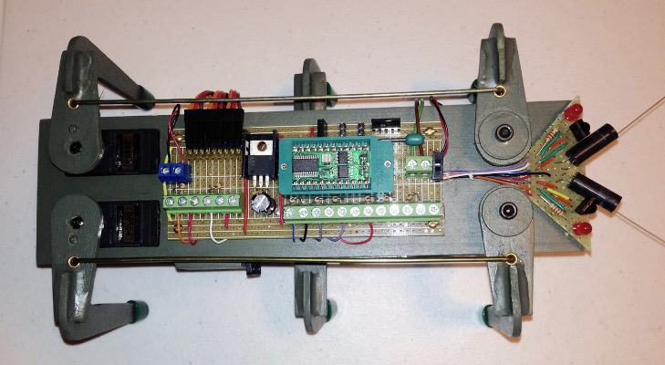
The circuit board design has some extra headers for future use, such as a "ping sensor, photo cell, and piezo speaker.
The project was fun and a great learning experience, being my first home built "bot".
Things learned and would do different in the future:
- The home soldered "carrier board" with screw terminals is fairly heavy, solder directly instead. Use a smaller 5 volt regulator, 100 mA
would have been adequate.
- Make the "bug's body wider, to accommodate the Parallax Board of Education, or the Super Carrier Board!
- Use the Board of Education, or the Super Carrier Board rather than making my own, "carrier board".
- Use a higher quality servo.
- Maybe stay to the original idea, keep it OEM, using the tactile navigation - feelers.
Material Used:
Spark Fun;
2 - SPDT switch, # COM - 00102
1 - Jumper wire kit, # PRT-00124
All Electronics:
1 - Breadboard, # SB-800
7 - 2 position terminal blocks, # TER-202
3 - 3 position terminal blocks, # TER-203
1 - TO-220 heat sink, # S-333
1 - 24 pin zif socket, # ZIF-24
1 - 1 x 40 pcb header, # SHS-40
1 - 4 x 1.5V AA Batt. holder
1 - 9V Transistor Batt. holder
Parallax:
1 - Bot Kit, # 28832 (used the parts from this kit to build the "bug-bot", including hardware, sensors, resistors, ect... ).
1 - Basic Stamp2 micro controller.
local stores:
hobby wood (bass), hardware, glue, paint, etc....
3 - standard size generic analog servos
6 - bolts caps used for the feet, they just happened to be green
my parts box:
5 Volt - 1 amp regulator
1 - 2 x 9 90 deg. header,
2 - front - rear legs ties - wire from a hanger
The "Stamp Bug type bot" may be a bit dated, classic compared to all the many articulated DOF machines and kits using the latest micro controllers available today, so "thank you", for reading the post.
The video:
("One of those time's putting off ordering one, until, now it is
no longer available.") Now I have the "bug" for one.
I ordered the "Boe-Bot" with the, "crawler kit", as an intro to "walking bots".
What a fun bot, what a great experience assembling and learning
the program routines to make it go! (More on that later in another post.)
The Boe-Bot's infared navigation system worked very nicely,
so I used it in my "StampBug2" type "bot".
The antenna feelers are not currently wired, just on for looks. The original "bug"
used tactile navigation through the "antenna feelers". (so much for keeping it OEM).
Applying what I learned building the "Boe-Bot",
most of the program routines are from the, "Robtics with the Boe-Bot" manual, version 3.0 by Andy Lindsay.
Copyriight by Parallax Inc. Some of the sensors and electronic components used
are from the "Boe-Bot" Kit from Parallax Inc.
It was a big help for the start of this project to review pictures of the "StampBug2"
and the bug's original Basic Stamp program. Kudos to the user's of this forum for those posts.
Of course, it is those same post's that reminded me that I wanted to "play" with one some time ago.
The body and legs were cut from hobby wood (bass) obtained from a local art store.
The legs were cut to include the OEM interlocking horizontal to vertical joints.
I don't have a pattern for them to include with the post, I drew them directly on the wood
itself (should have traced them out first, before I glued them together). The bolts, nuts, spacers,
and washers were obtained at our local hardware store.
The body was painted a olive green color.
The original program (and robot), "BUG.BAS" was based on the 8 bit Basic Stamp,
and used touch "feelers" to navigate. The program was efficiently
written to use the limited memory of the Basic Stamp.
I used the Basic Stamp 2, with more memory and
variables, the walking routines are written out
in sub-routines, making them easy to follow.
The original program actuated all three servo's at once for a nice smooth walk!
It seems the generic servos I used may be current hungry?
When operating the three servos at the same time,
it draws the voltage down on the batteries causing the servos to work erratically?.
Same for the Basic Stamp2, so I added the separate 9 volt transistor battery for the BS2,
and actuate only two servo's at a time. (The fix worked.)
As a result, the walking routines move the left and right legs separately, which slows the bot's walk.
(I really wanted to actuate all three servo's - for fluid operation.)
The center leg servo works the hardest and must be continually actuated to keep the right or left
side from drooping back down. I may try different servo's in the future.
The "bot" also seems to "crab" a bit, on hard surfaces, one direction, and on the rug, the other direction,
with no change in the servo parameters. Maybe better gripping feet, or shorten the stride may help?
The circuit board design has some extra headers for future use, such as a "ping sensor, photo cell, and piezo speaker.
The project was fun and a great learning experience, being my first home built "bot".
Things learned and would do different in the future:
- The home soldered "carrier board" with screw terminals is fairly heavy, solder directly instead. Use a smaller 5 volt regulator, 100 mA
would have been adequate.
- Make the "bug's body wider, to accommodate the Parallax Board of Education, or the Super Carrier Board!
- Use the Board of Education, or the Super Carrier Board rather than making my own, "carrier board".
- Use a higher quality servo.
- Maybe stay to the original idea, keep it OEM, using the tactile navigation - feelers.
Material Used:
Spark Fun;
2 - SPDT switch, # COM - 00102
1 - Jumper wire kit, # PRT-00124
All Electronics:
1 - Breadboard, # SB-800
7 - 2 position terminal blocks, # TER-202
3 - 3 position terminal blocks, # TER-203
1 - TO-220 heat sink, # S-333
1 - 24 pin zif socket, # ZIF-24
1 - 1 x 40 pcb header, # SHS-40
1 - 4 x 1.5V AA Batt. holder
1 - 9V Transistor Batt. holder
Parallax:
1 - Bot Kit, # 28832 (used the parts from this kit to build the "bug-bot", including hardware, sensors, resistors, ect... ).
1 - Basic Stamp2 micro controller.
local stores:
hobby wood (bass), hardware, glue, paint, etc....
3 - standard size generic analog servos
6 - bolts caps used for the feet, they just happened to be green
my parts box:
5 Volt - 1 amp regulator
1 - 2 x 9 90 deg. header,
2 - front - rear legs ties - wire from a hanger
The "Stamp Bug type bot" may be a bit dated, classic compared to all the many articulated DOF machines and kits using the latest micro controllers available today, so "thank you", for reading the post.
The video:
800 x 440 - 80K

1243 x 1612 - 123K
800 x 552 - 101K

1280 x 742 - 137K
729 x 400 - 108K


775 x 400 - 96K
Comments
http://forums.parallax.com/discussion/123237/byo-walker-on-the-cheap
http://forums.parallax.com/discussion/149087/very-old-milinst-stambug/p1
I've been hoping to adapt the same concept to the Parallax Hackable Electronic Badge. It's also really small and cute, as shown in the prototype below. I didn't get any further than the initial drawings and a single prototype because the Parallax travel season suddenly picked up.
Ken Gracey
Great work Douglas M! Love the triangular "head" board... Extremely neat construction and details
Ken - can't wait for this...
Would buy a kit like either of these!
I really need a way to cut or print parts! My sister does have access at Louisiana Tech where she teaches... Um?
Between this and the Toddler which you guys bought for me, I'm starting to look like the Forum freeloader! Thanks again to Mike and everyone who was in on the Toddler deal. You guys rock!
That's a really simple crawler.
I should post where we (my grandsons an I) are up to. We just have the platform and legs mounted. Next job is to mount the 3 servos which are made from 75x2mm rods bent.
Douglas,
That's a neat cricket you should be proud of. Thanks for posting.
Ken,
Another interesting design. Amazing to see how the different versions of legs are being used on these crickets.