

HB-25 connected to Raspberry Pi problems
 toby
Posts: 4
toby
Posts: 4
Hi all, my first post.
I'm trying to connect my Raspberry Pi 2B to my HB-25 with no luck (so far)
I tried connecting my Pololu MiniMaestro24 and all works well.
I then replaced the Maestro with my Raspberry Pi (no other wiring changes) and nothing (scratched head)
The Meastro has its down windows app which is nice and easy for testing where on the Raspberry Pi I wrote some Python Code which is below
import RPi.GPIO as GPIO
GPIO.setmode(GPIO.BOARD)
GPIO.setup(35, GPIO.OUT)
p = GPIO.PWM(35, 50)
p.start(50)
Basically the code above is using pin 35 at 50Hz and 50% Duty Cycle. I know this is all good for I connect my oscilloscope and saw the PWM signal from the Raspberry and as I change the Freq. and Duty Cycle the reading on the oscilloscope corresponded. (scratched head again)
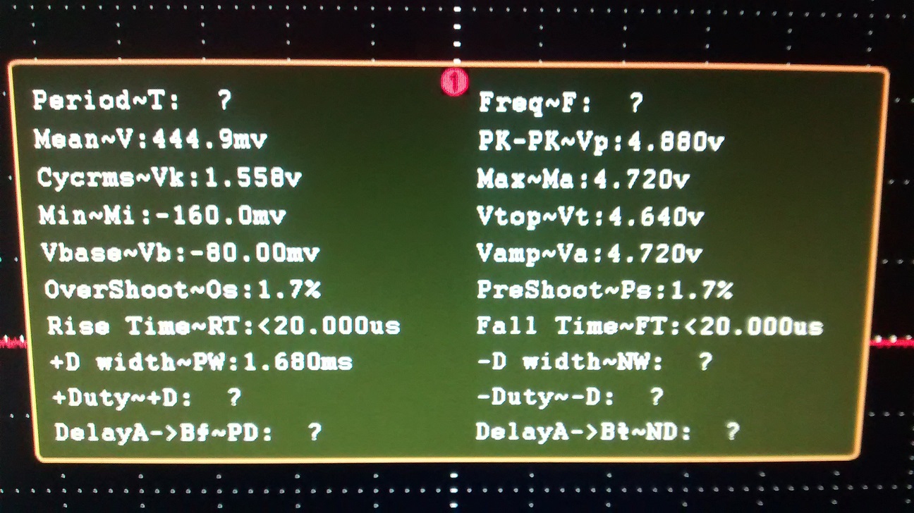
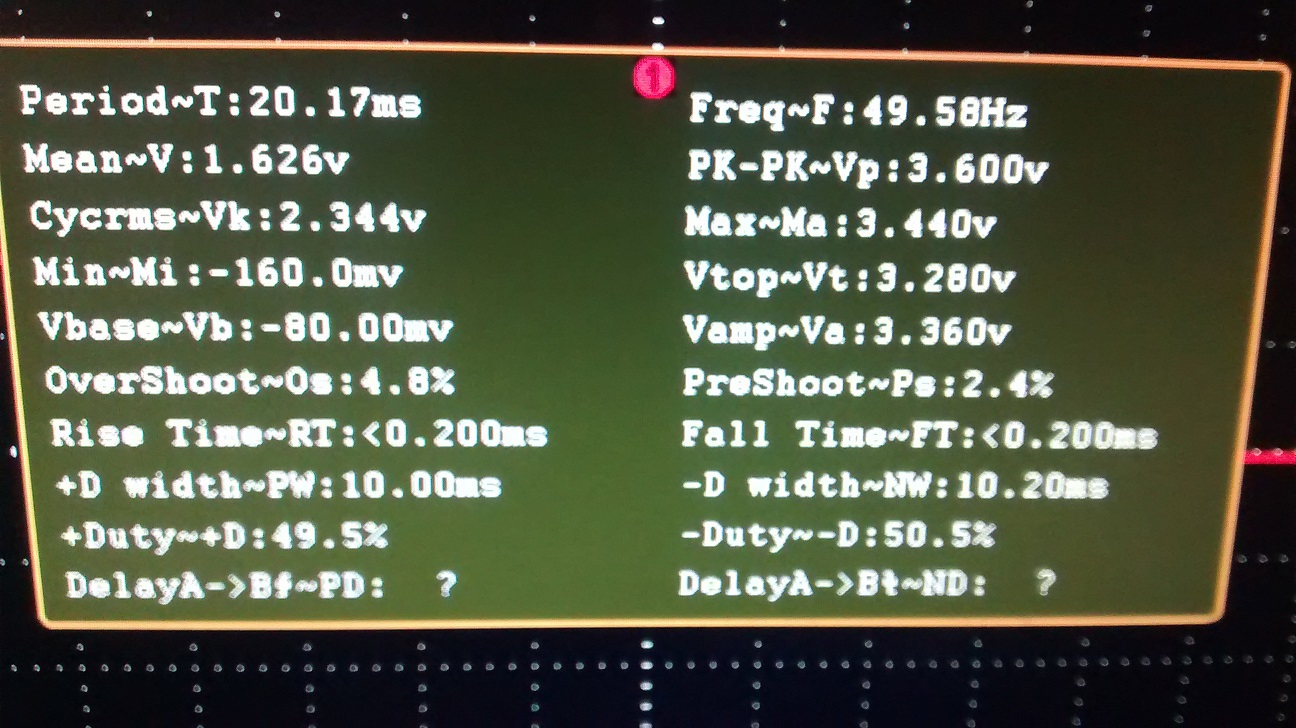
I then asked my oscilloscope to give me all the info on the signal it was seeing the the results are below (screen shots attached)
Maestro
Raspberry
This is were I get in a little over my head.
Can somebody have a look at the stats and well me where the problem maybe ? I notice the Max~ma Voltage is down from 4.72 to 3.6V and was thinking maybe this is too low for the HB-25 and PK-PK (peak to peak) is 4.88 compared to 3.6V are these voltage values too low for the HB-25 to pickup ? or am I looking in the wrong area ?
Thanks again
Toby from Australia (Long way south for most people)
Hardware References:
Parallax HB-25 Motor Controller https://parallax.com/product/29144
Pololu MiniMaestro24 https://www.pololu.com/product/1356
Raspberry Pi 2B https://raspberrypi.org/products/raspberry-pi-2-model-b/
Power Supply elecrow.com/b3603-dcdc-digital-control-stepdown-module-p-766.html
oscilloscope Owen ds7102V owon.com.hk/products_info.asp?ProID=172#sthash.9dLmIAKp.dpbs
Comments
That's much too high of a duty cycle. You want it to be 7.5%.
The HB-25 behaves a lot like a CR servo. A 1500us pulse will stop the motor and shorter pulses will cause the motor to move one direction and longer pulses will cause the motor to turn in the other direction.
It would be a good idea to practice with a normal hobby servo since the HB-25 responds to the same sort of pulses.
The HB-25 should work fine with the R Pi's 3.3V logic. A lot of us use the HB-25 with the 3.3V Propeller.
Thanks Duane for your quick reply.
I tried 7.5, 10, 12.5 as I found in a number of other RPi python post but nothing
I have attached a picture of the setup below. I have removed the 5V white wire going to the RPi from the HB-25 (R pin) for it makes the Pi freeze.
I have also measured the voltage across M1&M2 (outputs to motor on HB-25) and nothing. When the Maestro was working I measured 11.5V
frogmore.com.au/Setup_hb25_RPi.jpg
Also just tried connecting a servo to my RPi and it works like a charm.
Feeling lost.
Edit: This doesn't explain why it works with the Maestro.
Could you also upload a photo of the Maestro connections?
It looks like you're regulating the power to the HB-25. I would suspect a power supply issue except it doesn't explain why it works with the Maestro.
To do so, you have to produce 50 pulses/second that are within the pulse width limits of something less than 2 ms and something more than 1 ms pulses.
And even then, if you hit the center of the pulse width limits, the motor will try to remain stationary. You need to be a bit higher or a bit lower to get rotation.
Perhaps you should review the HB-25 documentation for wiring advice.
1.5 ms pulse will try to hold position, so try 1.25 or 1.75 ms for pulse width in a loop that is 20ms or less. (1/50th of second = 20 ms)
Of course, if your wiring is sloppy - all sorts of hazards come into play. Even serious damage to the various devices you are using. So check your wiring set up first and make sure it is correct, stable, and duriable. Verify all ground connections and that supply voltages are within safe bounds.
If a servo works, but not the HB-25, Check if you blew a fuse.
The HB-25 doesn't require 50 pulses per second. Unlike a servo, the HB-25 doesn't require continual refreshing.
It's often easiest to just treat a HB-25 like a CR servo so this difference is usually not important.
This still seems to be more of a wiring problem or a blown fuse as the OP claims an R/C servo works fine on the same interface that the HB-25 was connected to.
Thank you Duane Degn, and Loopy Byteloose for your replies. With your help I worked it out and yes some more reading.
I was a little high in my Duty Cycle,
using 100Hz Freq my Duty Cycle need to be 10 for 1ms pulse and 20 for 2ms pules with 15 being 1.5ms and neutral.
I think the Raspberry Pi is a little out for I need to use 14.6 to get a reading of 1.5ms on the oscilloscope plus the HB-25 backs this up by stopping the DC motor. Where at 15 I measure a duty cycle on the oscilloscope of 1.6ms plus the motor turns clockwise slowly.
All good now I know the tolerances and this gives me something to work with.
Also worth noting looks like I will need to get a dedicated PWM daughter board for the consistency of the PWM signal when I start placing a load on the multitasking OS becomes a little inconsistent and I see the motor moving a little from time to time.
Having a ball playing with this stuff, just need too disciple myself a little more to stop, think and understand some of the core concepts.
Thanks again to you both.
Thanks for the feedback. It's always good to hear progress being made, and it helps others down the line.
http://www.thegeekstuff.com/2013/08/nice-renice-command-examples/
I got the idea that the pigpio library gave the best results. Not that I have ever tried it.
A good place to start would be to find some servo control code. The HB-25 controllers use servo pulses as input. 1500us will cause the motors to stop. Pulses longer or shorter than 1500us will cause a motor connected to a HB-25 to turn.
Use joan's excellent pigpio http://abyz.co.uk/rpi/pigpio/ for much better results
-OR-
Add a RoboPi and use the RoboPi API - see the build manual and user docs at
http://www.mikronauts.com/raspberry-pi/robopi/
Full Disclosure: I designed & market my Propeller based advanced robot controller called RoboPi