

Cluso's new Propeller stackable and pluggable boards (MultiProps too)
 Cluso99
Posts: 18,071
Cluso99
Posts: 18,071
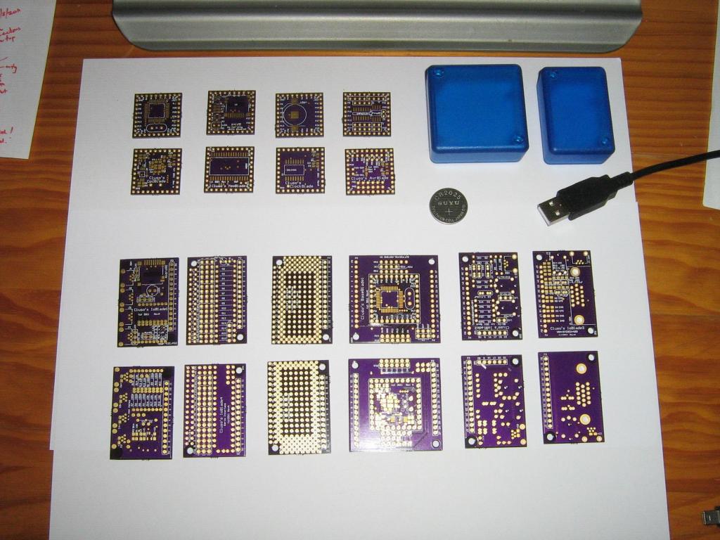
I have just received some of my new pcbs back. Here is a photo of them.
For reference, the coin cell battery is a CR2025 (20mm = 0.8" dia), and a USB cable. The boxes are Hammond 1551 and the pluggable pcbs are designed to fit them.
The top 2 rows are 1"x1" and stackable with the top side shown in the top row and the reverse side underneath. They are CpuBlade (Prop); MemBlade (SRAM + microSD); ClockBlade (RTC + Battery 1225); AvrBlade.
The lower 2 rows are 1.2"x1.76" & 1.76"x1.76" boards and pluggable with the larger one in the centre being the Prop board which the others plug into. The stackables can stack onto this pcb. They are IoBlade1 (microSD & 4x I2C/PS2); IoBlade4 (Servo Interface for Quad/Hex/OctaCopter, etc); IoBlade5 (a prototyping IO board); BaseBlade1 (Prop, xtal, Eeprom, 3V3 regulator and transistor reset cct and contains a copy of CpuBlade at it's center); IoBlade2 (TV, Stereo, I2C/PS2, Exp4); IoBlade3 (VGA, Stereo, I2C/PS2).
Can anyone pick the error?
Post #18 contains a Description of the pcbs.
Post #21 contains Multiple Propeller configurations.
Here is a link to the specs thread http://forums.parallax.com/showthread.php?132769-Cluso-s-miniature-stackable-and-pluggable-boxable-propeller-boards-(1-quot-x1-quot-etc)&highlight=cluso%27s+stackable

1024 x 768 - 120K
Comments
Not knowing the holder used, but it looks like the SD card holder on the IO Blade 1 is facing the wrong way.
Mac. Holder for uSD Cluso use have that placement of pads.
Oh, ok. The part I use has different orientation.
The IOblade1's mounting holes aren't drilled - that looks like an error.
Colors are all to do with cost! As I understand, any color can now be made. Actually pink on powder blue would be nice, if you are into that sort of thing
As Sapieha said, I use a different microSD socket from DigiKey. It is easy to hand solder because the pins are at the front and exposed.
I also have a set of tiny pcbs coming (some 0.6"x0.75") that just have simple blocks with headers to connect to any prop. They include: microSD; Clock (RTC); FT232RL (PropPlug with a twist); etc. They are designed to be really cheap add-ons specifically for hobbyists. I will post these on a separate thread as soon as they arrive (maybe today?).
Here are some photos showing the stacking. Remember these pcbs are a tiny 1"x1" (~25mmx25mm). They are smaller than the center of the protoboard that is sometimes cut out!
The pics show the connectors un-soldered. The connectors I supply are 4@ 1x9 pin female headers with extended pins and total length ~18.5mm. They female section is 11mm but has a 0.1" spacer which can be removed (its a bit tight so a little tedious) to lower the pcb spacing. This leaves a small gap between the stack of just under 1mm. I did this on the CpuBlade.
I also showed the BaseBlade1 which has the horizontal plugging ability as well as the stack. BaseBlade1's maybe daisy-chained. Multiple props the easy way
I will offer these assembled or as a kit of parts for those who would like to try smt. Be warned though, some of these pcbs are very tight to solder by hand.
And a few warnings...
* The ClockBlade cannot take the xtal socket pins
* The MemBlade (with the microSD) needs to be on the top of the stack because you need to trim the connector pins on the top of the pcb to insert and remove the microSD. This is not a design fault - there is no space!
* The ClockBlade requires the CR1225 battery to be inserted before soldering the connector. The battery cannot be changed, although it should last > 5 years! I am considering refining the pcb to have the option of a more expensive (another $1) battery socket which permits battery removal. I am using the expensive RTC DS1340C-33 which has an internal xtal with tighter specifications.
And a few comments...
* The AvrBlade has the ATtiny84 fitted. The ATtiny85 is not fitted (forgot to order one). The pcb supports either or both. Most I/O pins are brought out on headers. They can be programed by the prop using the SPI programming interface on their own header to connect to the prop (by a cable or jumpers) although I have yet to prove this. I have intended to use an I2C interface to the prop and they can be jumpered to pins 28 & 29 on the stack header.
* There are a few restrictions when using the MemBlade with other stackable blades because it requires the use of ALL P0-P29 pins!!! The microSD correctly shares these pins (as I have done with the TriBlade and RamBlade previously). The ClockBlade and AvrBlade have restrictions on their use with the MemBlade due to the sharing of these pins, as does the Prop's Eeprom
.
You need the obligatory "quarter" in the photos so people can see just how small these are
cheers
tubular
The processor board is the BaseBlade1 and has the identical circuitry in the center to the 1"x1" CpuBlade. This permits stacking vertically as well as plugging horizontally. BaseBoards can be daisy-chained end to end
You will see the RA pin header for the PropPlug side expansion has two mounting positions. This is so the pins can be kept inside the Hammond 1551 box if desired, and a male/female header used to extend the propplug. There is a pin header between these two connections providing an expansion for the I2C eeprom bus. There is a design trick to soldering these in the correct order and to prevent the I2C pins from interfering with the RA connector!!! Likewise, there is an expansion header on the other side for placing a daughterboard onto the 4pin daisy-chain connections instead. This is for the RamBlade3.
Also shown in the pic is the IoBlade3 that has a VGA, Stereo, and PS2/I2C via a miniUSB-B connector. This pcb will plug horizontally into the BaseBlade in either of the two 14pin (5V,Gnd and 12 I/O) expansion ports.
I have an alternative pcb (IoBlade2) that has TV, Stereo, and PS2/I2C, plus a 6pin 4I/O expansion port too.
BTW I have slightly reemed the xtal socket hole with a jewelers 0.9mm screwdriver and the sockets fit. Just a little too much plating. The socket pins can be carefully soldered on the top side, so the through-hole plating is not actullay required.
Now, I am about to trial stacking a CpuBlade onto the BaseBlade, and using the VGA, try two props driving the VGA in alternating lines to get higher VGA resolution. Fingers crossed
Tips:
* The plastic insulation on the male pin headers I am using can be removed easily.
* To create low profile links for short shunts, put the pins into the board from the top (as normal) but reverse the pins so that the long side of the pins go through the pcb. Solder them normally and cut the extra pins off. Now, on the top side of the pcb, carefully remove the plastic holding the pins together (they are now soldered so they no longer require this plastic. Now you have short pins for using with short shunts.
* To create low profile header pins (to connect to female stackable headers, just follow the proceedure above for the shunts.
* To create the headers where the RA connectors are fitted underneath, use the same proceedure with a twist... Before you solder the straight pins onto the underside of the pcb, trim as close as possible and evenly to the pcb, then solder. Now loosen the plastic retainer as above, but this time do not completely remove. Then turn the pcb over to the underside and heat each pin in turn with the soldering iron, while pushing the pin with the iron until it is flush with the pcb. Now remove the plastic retainer. Now you can solder the RA header to the underside of the pcb.
CpuBlade
- A basic tiny 1"square vertically stackable pcb used as a building block for other modules which has...
- An overclocked capable P8X32A QFP44 Propeller chip with special decoupling capacitors
- A socketed Xtal (5.00MHz, 6.00MHz, 6.25MHz, 6.5MHz or 13.5MHz) for 80/96/100/104/108MHz operation (108MHz not fully verified)
- A 64KB EEPROM AT24C512B TSSOP8 with WE (write enable/disable solderable links)
- An onboard 3V3 MCP1700-3V3 LDO voltage regulator from 5V (can be bypassed by wire)
- An optional transistor reset circuit (enabled/disabled by solderable link) - (permits use of cheaper USB-TTL modules that do not include the transistor reset circuit instead of a PropPlug or equivalent)
- Can be stacked with other stackable modules...
- Run parallel Processors
- Can be stacked by not fitting, fitting RA pins or cutting the pins which are not to be common between processors
- Multiprocessor solutions for higher resolution VGA and perhaps TV video
- Perhaps useful with Baggers & Coley's PropGFX
- Other Propeller based multiprocessor solutions
- Stack with MemBlade to give a super-fast latchless 512KB 55ns SRAM and microSD interface
- Equivalent RamBlade for running self-hosted propeller solutions including the CPM emulation running ZiCog, Sphinx, etc
- Stack with ClockBlade to add an RTC and Battery backup to the MemBlade/CpuBlade solutions.
- The CpuBlade+MemBlade+ClockBlade stack forms a RamBlade3 equivalent which can be further stacked to yet another CpuBlade to give the extra I/O capability required
MemBlade- A basic tiny 1"square vertically stackable pcb containing...
- A 512KB 55ns SRAM latchless design for maximum speed
- A microSD socket for microSD cards and FAT16/FAT32 or other formatting
- Led for indicating microSD access
- An onboard 3V3 MCP1700-3V3 LDO voltage regulator from 5V (can be bypassed by wire)
- Stack for use with CpuBlade
ClockBlade- A basic tiny 1"square vertically stackable pcb containing...
- A DS1340C RTC clock chip with internal high accuracy xtal
- uses I2C on the EEPROM pins P28/P29
- A socket for CR1225 Lithium Battery backup
- An onboard 3V3 MCP1700-3V3 LDO voltage regulator from 5V (can be bypassed by wire)
- Stack for use with CpuBlade
- Can also be used with other boards to provide RTC solutions
AvrBlade- A basic tiny 1"square vertically stackable pcb containing...
- An ATtiny 44/44A/84 14 pin micro with...
- 4 pin I/O expansion header with ADC option
- 4 pin I/O expansion header
- 4 pin ICP SPI programming header with optional shunt links to P4..P7
- An ATtiny 45/85 8 pin micro with...
- 2 pin I/O expansion header with ADC option
- 4 pin ICP SPI programming header with optional shunt links to P0..P3
- An onboard 3V3 MCP1700-3V3 LDO voltage regulator from 5V (can be bypassed by wire)
- Either or both ATtiny's may be fitted.
- I2C EEPROM P28/P29 header pins provided for wire links for I2C operation of the ATtiny's
- Intended to be programmed by the propeller.
- Stack for use with CpuBlade
- Can also be used with other boards to provide ADC or extra I/O solutions
- Note: Programming and code has yet to be written. This is just a concept.
BaseBlade1- A small 1.76"square pcb used as a building block for other modules which has...
- At the center is a CpuBlade circuit with stackable connector
- This circuit can either be built or not
- See CpuBlade specifications
- All stackable pcbs can be vertically stacked to this BaseBlade1 including CpuBlade
- This module is designed to fit into a Hammond 1551 R or S case (translucent blue available too) although vertically stackable boards may preclude this option
- This module also forms the basis of a series of "pluggable" boards that may be mounted in Hammond 1551 boxes
- Multiple BaseBlades may be daisy-chained using a 2/3/4 wire interface where the outputs of P12..P15 of the first connect to /Reset, P31, P30, and a selectable pin
- This permits the higher priority BaseBlade1 to download the lower priority BaseBlade1
- The highest priority BaseBlade1 is designed to connect its /Reset, P31 & P30 to a PropPlug or a new boxed equivalent available shortly
- By jumpers on the BaseBlade1, a lower priority BaseBlade1 may also reset its higher priority cousin, and this may also be passed by jumper to its higher priority cousin up the chain
- The last daisy-chained board may be a RamBlade3 (available in about 4-5 weeks). The RamBlade3 may also be mounted on top of the (last) CpuBlade in the same box.
- A series of 14pin (5V, Gnd & 12 I/O) horizontal expansion boards that fit into Hammond 1551 boxes are planned. These include...
- IoBlade1 A microSD and 4x I2C/PS2/etc (miniUSB-B) connections
- Status - mfg error - no holes drilled
- IoBlade2 VGA + Stereo + 1x I2C/PS2/etc (miniUSB-B) useful for Keyboard in PS2 mode
- Status - built and undergoing testing
- IoBlade3 TV + Stereo + 1x I2C/PS2/etc (miniUSB-B) useful for Keyboard in PS2 mode + 6pin (5V, Gnd & 4 I/O) horizontal expansion header
- Status - pcbs in hand, to be built and tested
- IoBlade4 Servo expansion (can plug on top) for up to 16 servo interfaces
- Designed particularly for QuadCopters (and Tri/Hex/Octa)
- Can also be used for controlling robots, etc
- Has separate series resistors on all servo pins for protection
- Has separate links for 5V on each servo pin (should be disabled for ESC connection)
- Use servo connections to connect to the Radio Control for Throttle, Aileron, Elevator, Rudder, etc
- 12 I/Os are directly connected to the BaseBoard1. The additional 4 I/Os require a cable header connection
- Completely thru-hole design for user assembly
- Status - pcbs in hand, to be built and tested
- Note: I have not done any code yet, but others such as Jason Dorie have QuadCopters running with the propeller chip. Ken Gracey has built a QuadCopter using a commercially available Propeller based solution
- IoBlade5 A prototype pcb 1.2"x1.76"
- Status - available
StepperBlade (Stepper BaseBoard)- A 1.76"square pcb able to plug into the BaseBoard1 14pin expansion connectors
- A motherboard that will take 4x Cluso's A4982/A4984 Stepper Modules or Pololu A4983/A4988 Stepper Modules
- Designed for use with a RepRap 3D Printer such as the Mendel, Prusa Mendel, my Micro-Mendel (WIP), etc or hobbyist CNC devices
- 2x 2pin connectors for V+ & Gnd input (often 12V)
- 4x 4pin connectors for 4x Stepper Motors (typically Nema23) control (2A max, although deration may apply)
- Simple propeller interface for Step and Direction to each Stepper Module plus a common Reset and Enable line.
- 4 sets of 3 jumpers to select step rate for each motor control (1, 1/2, 1/4, 1/8*, 1/16*). *Note 1/8 and 1/16 are mutually exclusive on A4982/A4984.
- Status - pcbs due from mfr 9 Sept 2011
A4982/A4984 Stepper Module- A 0.6"x0.8" pcb compatible with Pololu's A4983/A4988 Stepper Driver
- Uses Allegro A4982 or A4984 stepper driver TSSOP28
- Simple Step and Direction interface
- A simple fixed resistor is used to set the current limit
- Large holes for easy desoldering if required
- Pololu uses a potentiometer which requires a harder setup proceedure
- Step rate connections for 1, 1/2, 1/4, 1/8*, 1/16*. *Note 1/8 and 1/16 are mutually exclusive on A4982/A4984
- Status - pcbs in hand, to be built and tested
MOSFET Driver- Small pcb (to be designed - WIP)
- Designed to drive heater on RepRap style 3D printers: Extruder, Heated Plate, etc
- Can be used for other controls such as robotics
- P Channel Mosfet with 15A drive (normally 12V)
- ATtiny84 micro controlled ???
- Screw terminals
- Simple 1 or 2 wire interface to the Propeller (set temp and forget)
- Sensor circuit for Thermister temperature sensor to 300C
- ATtiny ISP SPI programmed by the Propeller using 4pin header
- Status - design still WIP
Most of these stackable and pluggable boards should be able to be simply connected to other propeller platforms.These pcbs are in addition to my other "Cheap and tiny modular pcbs" which are just building blocks on this thread http://forums.parallax.com/showthread.php?134219-Cluso-s-cheap-and-tiny-modular-pcbs...
Good descriptions and it's very impressive to see all that you've accomplished with these small boards in one post - i.e. you've masterminded a great deal of hardware. It's good that you can specialize and let others write the software for their intended apps.
Here are some examples...
The first and second pics show a CpuBlade stacked on top of a BaseBoard1. By inserting an extra set of stacking connector(s) between the BaseBlade1 and CpuBlade, various configurations of parallel connections between propellers are possible without making cables or soldering wires! These stacking connectors I use are 1x9 - they can be cut down or just simply remove the pins from the housing. This configuration connects 5V & Gnd (obviously required) plus P8..P23.
On the BaseBoard1 I have connected an IoBlade2 (just the TV section has been soldered today) to P0..P11 (the TV will use 3 pins P4..P6) and an IoBlade3 (I am only using the VGA) to P16..P27 (the VGA will use P16..P23). The BaseBoard1 propeller will drive the TV using 3 pins P4..P6 and the CpuBlade propeller will drive the VGA using 8 pins P16..P23. Note, there is no protection between the common propeller pins P8..P23 so do not make a programming error or you may damage the prop chip(s)!
To the right in the pics is my TriBlade. I am only using this temporarily to provide both 5V and the PropPlug section for downloading code. As soon as I get time I will build my new PropPlug replacement (see this thread http://forums.parallax.com/showthread.php?134219-Cluso-s-cheap-and-tiny-modular-pcbs... I will be doing a boxed version shortly too).
Note how simple this parallel connection was to construct. It is just as easy to pull the modules apart and replace with a different set of extra stacking connectors between a different set of prop pins to form a new parallel configuration.
You may well ask why I have constructed this particular configuration. Well, I want to try driving the VGA with 2 propellers, each alternating displaying a horizontal line in the display frame. This way I have P16..P23 of the props in parallel and I have P8..P15 at my disposal for communicating/synchronising between the propellers. This should enable me to get a higher resolution VGA
Other Multiple-Propeller configurations...
The next picture shows an example (not really soldered) of how the daisy-chaining between multiple BaseBlade1's. Of course, each of these BaseBlade1's may in turn be multiple propeller stacks.
And yet another configuration (sorry, no picture, at least for now) is a vertical stack of BaseBlade1's where the 14pin expansion ports can be used for separate expansion boards. I have a prototyping board available. The stacking of these boards would be just as for the previous example of stacking CpuBlades, but instead of using CpuBlades, substitute BaseBlade1s. The stacking would still use the 1"square center pins, and the parallel connections between propellers would be made using extra stacking headers as before.
Thus, the combinations of multiple propellers are almost endless with just a few simple modules.
RamBlade3 (when available) and the exsting RamBlade can add to this mix.
Enjoy
Note that I have not yet trimmed the lid of the box (the rim needs filing) to let the connectors (on the underside of the pcb) sit into the lid recess.
I have setup a new website (far from complete) that starts to detail the different boards. There is more at the start of this thread as far as specifications go. However, the website details the pcb costs. While I have listed assembled pcbs, at the moment I am still short on time so will not be offering much of this. Bare pcbs and pcbs with most parts are listed.
Its also a way for any of you wanting to try out smt. Some pcbs are harder than others, but with good glasses, fine temp controlled soldering iron, fine solder and flux pen, all is pretty good.
Here is my new website... www.clusos.com/home
I used a new software package to setup my website and didn't realise I was naming the filename when I called my home page "home". Now I have to get ftp running to put a dummy index.htm page there!
The ATTiny84 has 4 I/O pins and 4 ADC pins available on headers.
The ATTiny85 has 2 ADC pins on headers.
Comms to the prop could be I2C or 2 wire serial, or even SPI (without using the external available pins).
There is a 3v3 regulator on the pcb.
I am still considering what I will use the Avr's for... This pcb is just to provide a basis to connect them to the prop. Here are a few ideas...
1. Make a cheap USB for the prop
2. Touch panel interface to the prop (I have already done this directly with the prop)
3. Jazzed has done I2C to PS2 keyboard and mouse
4. Test out a mosfet driver to control the temperature on the extruder and heated bed in a RepRap/Mendel 3D printer project
5. Something else???
The MemBlade features a microSD, 512KB 55ns SRAM and a 3V3 regulator on a 1"x1" pcb designed to stack onto my CpuBlade 1"sq pcb or my BaseBlade1 1.8"sq pcb.
The SRAM address A0-18 is on P0-18, data D0-7 on P19-P26, -CE on P27, -OE on P28 shared with SCL, -WE on P29 shared with SDA. This is a non-latched design although by interposing a small pcb between the BaseBlade1/CpuBlade, a latched design could be simply implemented.
The microSD uses -CS on P23 (and requires -CE=P27=1), DI on P22, CLK on P21, DO on P20. An LED is on -CS to indicate microSD selection/access.
The propeller I/O and programming is via P30/31.
These two pcbs form a RamBlade3. The ClockBlade is an RTC with battery pcb 1" sq and can be inserted between the BaseBlade1/CpuBlade and the MemBlade, and runs of the I2C Eeprom pins. The ClockBlade is yet to be tested.
Here is a pic of the working setup together with my USB module which derives power from the USB port
I'm trying to find an appropriate chip to use on the MemBlade.
This one at Digi-Key looks promising. Would it work on your MemBlade?
http://www.futureelectronics.com/en/technologies/semiconductors/memory/static-ram/asynchronous/Pages/1039023-AS6C4008-55SINTR.aspx?IM=0
You will also require a 74LVC1G97DBV
Thank you for the link to the SRAM.
A search for the gate at Future Electronics didn't produce any hits but I found this at Digi-Key. Is the Digi-Key 74LVC1G97DBV the correct part (I only see the one package type)?
I haven't been able to find a schematic for the memBlade. I'm hoping you can help me select the remaining parts I'll need to complete the board.
I think I can figure out what uSD socket to use (I probably have one).
I figure R3 is the current limiting resistor to the LED so the value isn't important as long as it's at least 100 ohm.
I'm guessing Q1 is the MCP1700-3V3 LDO voltage regulator and C0 and C1 are the regulator's caps (IIRC 1uF each).
It looks like R2 connects with a pin of the logic gate. A glance at the datasheet didn't provide me with any clues of the value of R2.
I'm also at a loss as to the values of R1 and C2. If I were to guess, C2 is a 0.1uF cap but only since it seems to be a common value used to bypass ICs.
Again, thanks for including your designs on the Smorgasboard. I look forward to trying these boards out.
I have since done a new revision of the schematic (but no pcbs done). The differences are:
- Uses a resistor network instead of separate resistors
- The pinouts of the 1"sq module are incorrect
Parts List is as follows:The 74LVC1G97DBV - "DBV" specifies the package (see the datasheet) so yes the one at Digi is correct.
I never use anything less than 1K (I usually use 3K-5K) to drive a LED. These days it is just a waste of power since superbright leds are cheap.
It is nice to see someone building these boards.
CpuBlade Construction
- I solder 4 @ 1x9 male pin headers using a trick - I solder the reverse side of the pins and then remove the plastic mounting material from the pins which leaves the pins sticking out both sides of the pcb. Then you can attach to both sides of the board.
MemBlade Construction- Place the pins/sockets temporarily ar each end of the SRAM before you solder the SRAM. Its position is critical to permit the headers to be straight.
- When you solder the MemBlade connectors, make sure that AT LEAST the pins on P18-P23 do not protrude above the pcb (i.e. cut them first slightly below the pcb edge so the solder goes into the hole). Otherwise, you will not be able to plug the microSD card in/out of its socket!
- I use 4 @ 1x9 Female socket with long pins (stackable headers) but you can permanently join to the CpuBlade with normal male pins instead.
I can supply the stackable headers if you want - by unregistered mail takes ~10-14 days from Oz ($1 per set of 4 @ 1x9 stackable + post $3)I'm glad you see it that way. I feel like I've been pestering you.
Thank you for the help.