

Homemade StingRay
 Ron Czapala
Posts: 2,418
Ron Czapala
Posts: 2,418
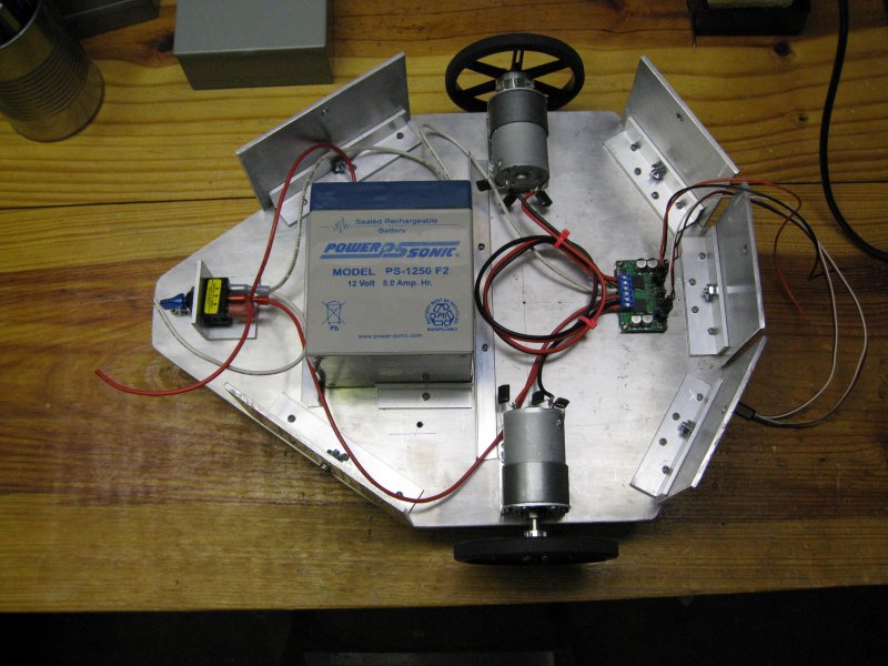
Here are some pics of my homemade StingRay. It is 13.75" x 10" x 4" (changed height to 3")
I am using:
I layed out the pattern on large graph paper and cut it using a jigsaw, hand hacksaw.
Hours of filing the edges to finish shaping it up...
Then I sanded it for hours with wet/dry sandpaper (350, 400, 600 & 1000)
and used Mothers Mag &Aluminum Polish to buff it out.
Not sure what microcontroller I will use - maybe a Propeller or even a BS2.
I have Pings and Sharp GP2Y0A02YK0F IR distance sensors 20 to 150 cm for object detection.
Current video & pics
See web site pictures
I am using:
-
Pololu 350 rpm 12V 29:1 Metal Gearmotors
- Pololu Dual MC33926 Motor Driver Carrier
- Pololu 90mm wheels with 6mm aluminum hub adapters
- 7Ah gell cell battery (changed to 5AH)
I layed out the pattern on large graph paper and cut it using a jigsaw, hand hacksaw.
Hours of filing the edges to finish shaping it up...
Then I sanded it for hours with wet/dry sandpaper (350, 400, 600 & 1000)
and used Mothers Mag &Aluminum Polish to buff it out.
Not sure what microcontroller I will use - maybe a Propeller or even a BS2.
I have Pings and Sharp GP2Y0A02YK0F IR distance sensors 20 to 150 cm for object detection.
Current video & pics
See web site pictures
800 x 600 - 91K
Comments
Discovered Mothers Mag &Aluminum Polish!!!
Switched to 5AH 12v gell cell
Very nice! Will enjoy watching this project come together.
Since you seem to love sanding so much, could you come sand my wood working projects for me?
Tony.
What are your plans for a power source?
I am planning to to use a 12V, 7 ampere/hour gell (see new pictures above) but I might get a smaller, lighter gell cell.
The chassis weighs 4lbs 3oz by itself and the battery weighs 5 lbs. The motors have 110 oz-in of torque (each).
This is my first robot (besides the BOE-BOT) so I don't know if this is too much weight.
Any opinions out there???
Are You going to clear coat it so it stays shiny like a delorean? or are You gonna Bling it with Pimp Striping?
As for the Weight, You could drill holes, and or cut slots to help lighten the load some.
You will want to shed some Pounds when You get all Ten Pings up and running...
Anyways, Looks like you are having some fun, and can't wait to see the finish You apply.
-Tommy
Hi Ron,
You have done excellent work!
Your chassis looks great and very professional!
If I were you I would use the Motor Mount and Wheel Kit with Position Controller.
If you worry about the weight, these motors is the best choice. Believe me they worth their money!
Their quality is fantastic! Words and pictures are not enough to describe them. If you adapt these kit on your robot you will realize the difference!
I'd love to use the Parallax Motor/Wheel kit but the price is a bit steep.
Your four wheeled robot is really impressive. In fact, it is probably what made me decide to built one...
I reduced the height by an inch and mounted the motors and wheels.
Next comes the electronics...
- Ron
I only see one problem, how do you work on such a clean work bench?
Tony
I've also been looking for a good excuse to get a TIG welder and a plasma torch!
Paul
That certainly would have looked much better but I'm sure it would have added substanially to the cost.
I really only used the jigsaw to cut the 27.5" x 21.5" sheet of aluminum into 4 pieces. I clamped a straight edge to the workbench, but it was still a pretty jagged cut.. The hacksaw and lots of filing were the main shaping tools.
I made brackets from 1/8" angle aluminum and riveted them to the top and bottom plates.
I tapped the brackets and used socket cap screws on the top plate to allow easy removal.
It is nice and sturdy - I was able to stand on on the chasis - before adding motors, wheels, etc
Variance bewteen the motors causes it to veer to one side rather than going straight.
I need to figure out how tweak the PWM instructions to compensate...
The new motors are 200 RPM but with larger circumference wheels it calculates to 4.25 ft/sec and 170 oz-inch of torque.
Current video & pics
I see that you are now Prop-powered too. You could add some pins in the upper right corner of you Propeller Proto Board for you motor signal cables. I did that when I was learning the Prop on my Boe-Bot. The Proto Board is a great board and very reasonably priced.
You could also add a raised breadboard up front for experimenting (like the original Stingray).
What is next? What motors and encoders are you thinking of using?
And the most impressive feature... How do make the ZapBop disappear in the test video above?
Amazing!
Whit,
The new wheels are the exact same BaneBot wheels as the Stingray and use the same 6mm hubs.
The new motors I ordered are bascially the same Pololu metal gearmotors except they are slower: 200 RPM vs 310 RPM but more torque 170 oz-inch vs 110 oz-inch.
With the larger wheels, the speed will be about the same.
They have a two-channel Hall effect encoder is used to sense the rotation of a magnetic disk on a rear protrusion of the motor shaft. The quadrature encoder provides a resolution of 64 counts per revolution of the motor shaft.
I haven't tried programming the Propeller yet since I don't have the motors/encoders but I am scanning the OBEX for useful code. I have some SHARP IR distance sensors and PINGs to experiment with.
The tail "wheel" is a 1" ball bearing roller I found at Harbor Freight
-Matt
Thanks for all the info. I like the look of those encoders. The motors on the Parallax Stingray have extended shafts. I think they were planning for that sort of encoder. There was a thread where someone was trying something similar and have sucesss.
Good luck as you continue to develop this great bot!
Thanks for the all the encouragement!
Now the real fun begins - writing the Propeller code to make it navigate without gouging holes in my walls
or running over my Yorkie!
;-)
-Ron
Eight seconds into your robot's journey - the cloaking device implementation is extraordinary - it disappears completely!
I can see the hardware, (which is great BTW), but it gives no indication of the technology behind its cloaking capability - therefore I must assume that your *secret* is in the code... ;-)
-Matt
Matt, I accidentally used a flux capacitor for the H-bridge - guess it caused a six-second jump back...
I have some Spin code that is working well using the Pololu motors with Hall-effect quadrature encoders.
It uses the Quadrature_Encoder and PWM_32_v4 objects
This video shows ZapBot moving straight at 50% duty. The speed ramps up and ramps down when it nears the end of the run.
It was supposed to go 100 inches but it went about 102. More code tweaking...
It is pretty consistent based on tweaks made to the code. Right now it "brakes" rather hard so I need to ramp down the speed more gradually.
It calculates how many encoder pulses until the "destination" pulse count is reached and uses the current duty value to determine when to start ramping down the speed.
-Matt
I was trying to using the "absolute position" returned by the Quadrature Encoder object but it got messy so I switched back to using the ReadDelta function which apparently handles position and direction values more readily than my intitial attempts. (Since absoulute can roll over and/or go negative)
I placed a serial, 4 digit 7-segment display on the breadboard to display debugging type data- comes in handy!
More work to go on spins and turning...
Great job on the build. You should be able to leverage some of the Stingray code out there to give you a head start.
Robert