Hard Drive Stepper Motor - with high speed spin-up circuit
 Beau Schwabe
Posts: 6,576
Don't throw away that DEAD hard drive just yet...
I had a couple of western digital hard drives lying around that were DEAD. Initially I was going to just harvest the magnets from the drives, but I focused my attention towards the hard drive motor itself instead.
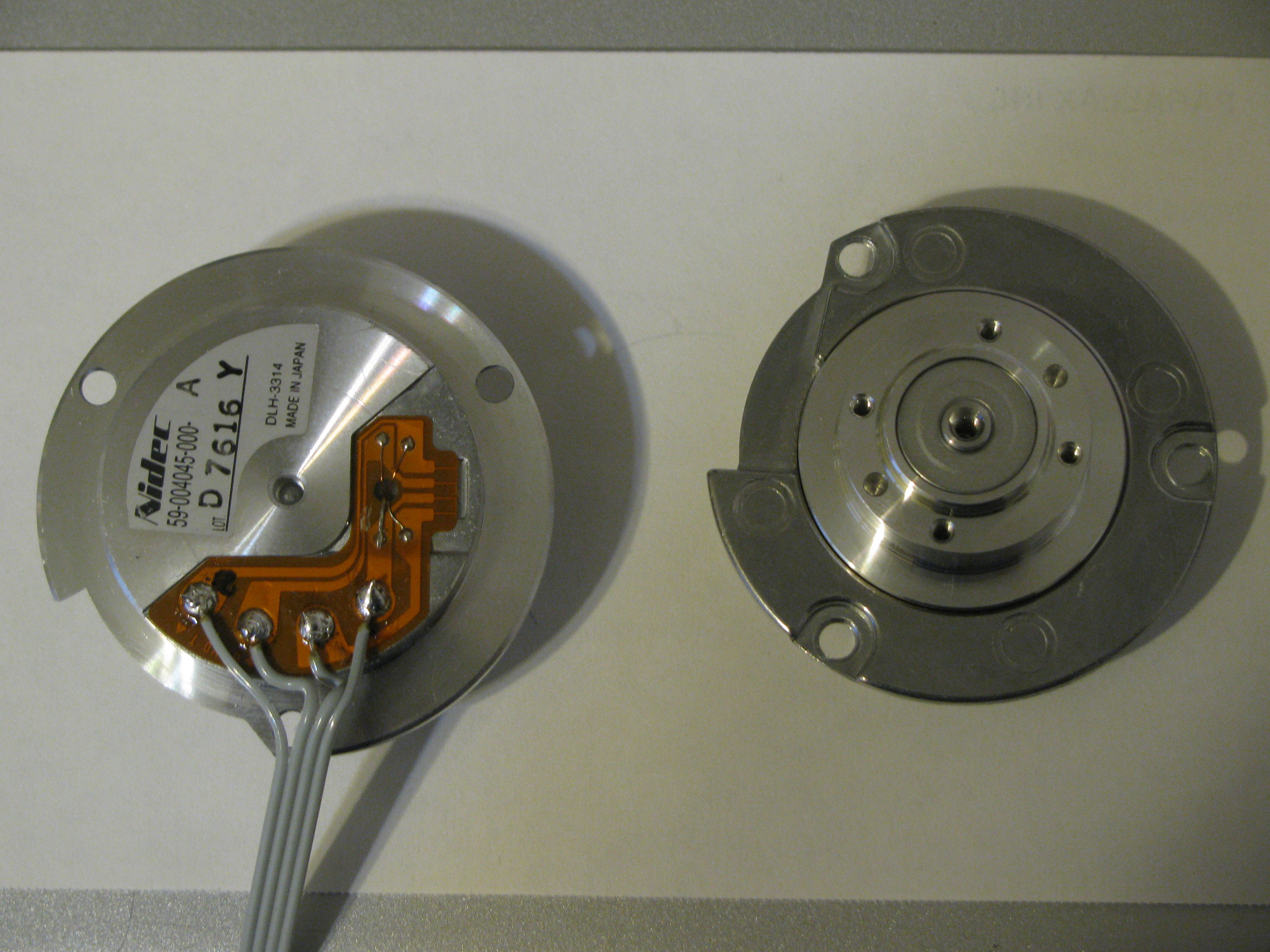
On the left hand side of the image, I just soldered 4 wires to the back of the motor. Normally these contacts make a connection with the circuit board via spring clips. Anyway I placed a black DOT that I will refer to as terminal #1, the others from left to right are #2,#3, and #4.
First I took an ohm meter and measured the coil resistances with the various combination possibilities with their results...
...I looked for the common denominator for the least amount of coil resistance and it worked out to be #4 ... so this is my common. (See Coils.jpg)
Next was to determine the sequence ... this was just by trial an error but here it is...
... Note the polarity. So A proposed driver circuit might be composed of 4 Half-Bridges (See HD Drive.jpg)
Edit
Here is a circuit that will spin up the hard drive to a high speed.
http://forums.parallax.com/showthread.php?p=881285
I just thought I would pass this information along (I hadn't seen Hard drive motors being re-purposed here in the forum)
The motors are 6 Phase 24 Steps per revolution or 15 Deg per step.
Enjoy!
▔▔▔▔▔▔▔▔▔▔▔▔▔▔▔▔▔▔▔▔▔▔▔▔
Beau Schwabe
IC Layout Engineer
Parallax, Inc.
Post Edited (Beau Schwabe (Parallax)) : 2/14/2010 2:43:56 PM GMT
I had a couple of western digital hard drives lying around that were DEAD. Initially I was going to just harvest the magnets from the drives, but I focused my attention towards the hard drive motor itself instead.
On the left hand side of the image, I just soldered 4 wires to the back of the motor. Normally these contacts make a connection with the circuit board via spring clips. Anyway I placed a black DOT that I will refer to as terminal #1, the others from left to right are #2,#3, and #4.
First I took an ohm meter and measured the coil resistances with the various combination possibilities with their results...
1-2   4.3 Ohms
1-3   4.3 Ohms
1-4   2.5 Ohms
2-3   4.3 Ohms
2-4   2.5 Ohms
3-4   2.5 Ohms
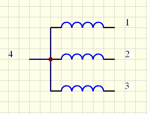
...I looked for the common denominator for the least amount of coil resistance and it worked out to be #4 ... so this is my common. (See Coils.jpg)
Next was to determine the sequence ... this was just by trial an error but here it is...
CCW     CW

+  -    +  -

4  3    4  3
1  4    2  4
4  2    4  1
3  4    3  4
4  1    4  2
2  4    1  4
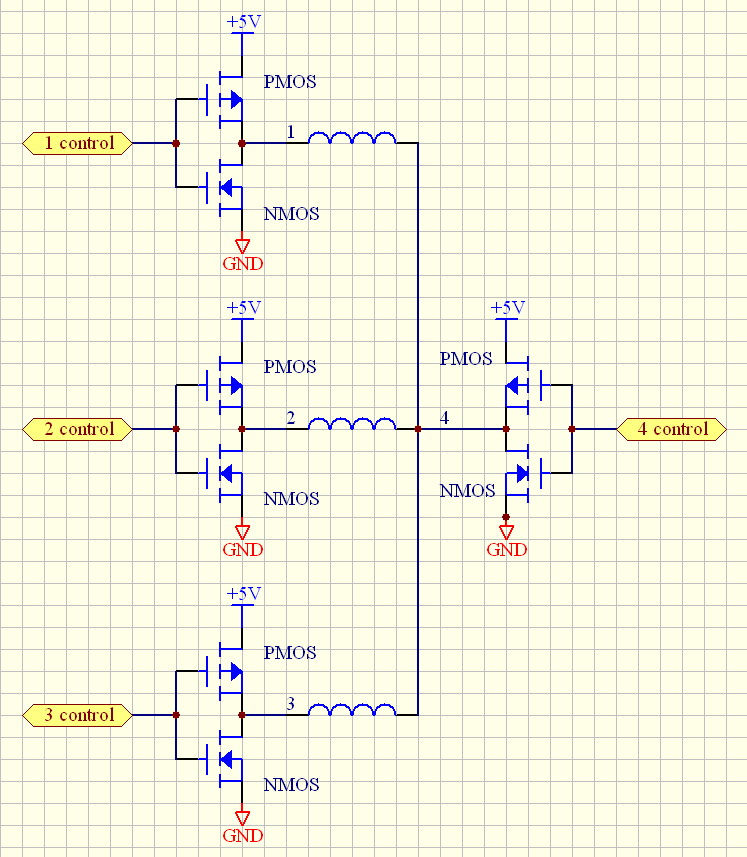
... Note the polarity. So A proposed driver circuit might be composed of 4 Half-Bridges (See HD Drive.jpg)
Edit
Here is a circuit that will spin up the hard drive to a high speed.
http://forums.parallax.com/showthread.php?p=881285
I just thought I would pass this information along (I hadn't seen Hard drive motors being re-purposed here in the forum)
The motors are 6 Phase 24 Steps per revolution or 15 Deg per step.
Enjoy!
▔▔▔▔▔▔▔▔▔▔▔▔▔▔▔▔▔▔▔▔▔▔▔▔
Beau Schwabe
IC Layout Engineer
Parallax, Inc.
Post Edited (Beau Schwabe (Parallax)) : 2/14/2010 2:43:56 PM GMT


Comments
And per Ken, keep cracking on that Prop2 layout! [noparse]:)[/noparse]
▔▔▔▔▔▔▔▔▔▔▔▔▔▔▔▔▔▔▔▔▔▔▔▔
·"If you build it, they will come."
Thanks... just trying to clean some of the clutter. I got the urge to dismantle the DEAD hard drive during the evening 10'oclock news and by mid-night I decided to post what I found.
Seems like a very capable little motor that might make a good little robot if you get a couple of them and put wheels on the hub.
Prettybird,
Thanks... The motor can be driven in 3-Phase if you don't flip the polarity, so yeah, technically it's a bipolar 3-Phase stepper, but there are a total of six Phase sequences before you see a repeat.
▔▔▔▔▔▔▔▔▔▔▔▔▔▔▔▔▔▔▔▔▔▔▔▔
Beau Schwabe
IC Layout Engineer
Parallax, Inc.
Post Edited (Beau Schwabe (Parallax)) : 2/10/2010 4:55:31 AM GMT
Why is that?
Is the stepper designed with a massive magnetic core that retains lots of residual magnetism, where the hard drive motor does not?
Does that mean the stepper was designed for lots of magnetic force at low speeds, but will be limited to only moderate top rotational speeds, where the hard disk motor will not have much low speed torque, but will be capable of much higher top speed? Does that sound right?
Beau, did the motor feel like it had much zero or low speed torque?
Are there any other differences that would affect how a motor like this could be used?
I was thinking that the hard drive motor could be used for a little 3 phase generator, but then realized that it probably would have to be spun at quite a high rate of speed to get any watts out of it... but then, I've got a little low-power high speed Stirling engine that might be a good fit for a generator like this!
at least a dozen. Always thought I would keep them for more drive storage space but then every couple of years newer
bigger faster drives come out that dwarf the old units in capacity. So as long as I have them, I may as well put them to
good use. What other components might I salvage from these? I heard the mention of magnets. Any other goodies?
Not meaning to hijack the thread and Ok with being moved if this is not the correct place but on the subject of stepper motors,
I purchased 4 motors on eBay @ $7.50 each and haven't been able to get them turning. And please, before I catch a barrage
of flack concerning "you get what you pay for", I just thought is was a nice price that I could afford to sacrifice even if I
couldn't get them going.
They had no datasheet, no manufacturer name, and no listed voltage rating. There is an ID sticker on the side with the part number
and deg/step value but thats about it. They appear to be in great condition and I was hoping someone here might have also purchased
these or know of a way to get the voltage rating and wire sequence to use in programming.
It is a 4 wire setup:
Brown, Orange, Red, Yellow
brown to red = open
brown to yellow = open
brown to orange = 14 ohms
red to yellow = 14 ohms
red to orange = open
orange to yellow = open
So, I can see the two circuits and I have had it connected to my PDB at one time at the L293 pins and could never correctly identify
the sequencing. I attempted this with 5v, 9v, 12v external supply voltages each time going through the possible combinations of the
4 wires and could never get more than a vibration out of the shaft. The motors are pictured below. I googled and yahoo'd them and
the only thing that came up besides more people selling them was a picture mentioning their use in a syringe pump. Any help would
be great
▔▔▔▔▔▔▔▔▔▔▔▔▔▔▔▔▔▔▔▔▔▔▔▔
and so, the journey continues..........
To several of your questions, I'm not sure, but I would guess that much has to do with the fact that most steppers (more motion precision) have less deg per step typically 1.8 Deg where the Hard drive motor (more speed precision) has 15 Deg per step.
I haven't done any torque tests with the Hard drive motors yet, but when I energize one of the coils with a 3.7 li-poly, it has a respectable amount of hold. The motors are probably meant for 12V but I haven't pushed it above 3.7V during any of my testing.
@eiplanner,
No need to feel like you are hijacking the thread, I was just offering a service ... The subject of stepper motors comes up in the forum from time to time so no big deal.
"I heard the mention of magnets. Any other goodies?" ... probably some good bearings in the read/write head but I haven't figured out how to get them out yet. Some of them have a clip, and others are moulded in plastic. The platters themselves are interesting, I have an idea for them but I'll save that surprise for later.
I would guess that your stepper motor is bipolar, meaning that to operate correctly you need to reverse the polarity to the coils. Since it has only two coils it's 4-phase and you almost have to reverse the polarity, otherwise it >will< just wiggle back and forth as you describe.
The two coils:
brown/orange and red/yellow
There isn't much that can go wrong with a stepper, the fact that you are getting an omic reading is good.
I would try this sequence:
To reverse the sequence, just reverse the polarity of one of the sequence pairs like this:
See if that doesn't do anything different... sometimes it helps to mark the shaft against the base with a Sharpie or something so you can see any net movement.
▔▔▔▔▔▔▔▔▔▔▔▔▔▔▔▔▔▔▔▔▔▔▔▔
Beau Schwabe
IC Layout Engineer
Parallax, Inc.
Post Edited (Beau Schwabe (Parallax)) : 2/11/2010 8:25:47 AM GMT
▔▔▔▔▔▔▔▔▔▔▔▔▔▔▔▔▔▔▔▔▔▔▔▔
and so, the journey continues..........
A stepper motor is a dc brushless synchronous motor is it not? Assuming you have enough kinetic momentum to carry it through, you can monitor the velocity of a stepper motor by not driving a particular step and reading the coil as an input device instead.
▔▔▔▔▔▔▔▔▔▔▔▔▔▔▔▔▔▔▔▔▔▔▔▔
Beau Schwabe
IC Layout Engineer
Parallax, Inc.
Post Edited (Beau Schwabe (Parallax)) : 2/11/2010 4:10:38 PM GMT
Post Edited (kwinn) : 2/12/2010 8:48:53 PM GMT
···· I am still a newbie, I am trying to build my own small cnc (larger cnc later) and I took a few printers apart and found these stepper motors, just thought I would share my headaches, maybe help someone elses headache be a little less. The printers where HPs and one Epson. The numbers I found on the motors are:
PM55L-048-HPG9
PM35L-048-HPD4
and of course the one I am sending a picture of
···· I found that, I hook the common to the +V and then apply -V to leads· A-for and B-for, in that order the shaft turns forward. -V to leads A-rev and B-rev, in that order the shaft turns in reverse.
I am guessing that instead of these being a regular 4coil stepper, they must be 2phase (if thats the right terminology).
Can anyone tell me if I can make these 4coil steppers, if so, how?
I have two old flat bed scanners I am working on next, trying to figure out the stepping sequence, they are also 5 wire.
Anyway, hope this might help someone in the future. As far as these specific printer motors. I spent a week trying to figure out how to sequence the 4 coils for these. And accidentally figured out the above sequence for them.
If anyone has any experiences with making a small cnc with Lpt printer port running TurboCNC and using steppers from scanners that wants to share, I would appreciate it greatly. I am thinking of useing the BS2 or the Prop to take the signals from the Lpt and deliver the signals out to the steppers.
▔▔▔▔▔▔▔▔▔▔▔▔▔▔▔▔▔▔▔▔▔▔▔▔
Dragon
http://www.piclist.com/techref/io/stepper/wires.htm
Duffer
▔▔▔▔▔▔▔▔▔▔▔▔▔▔▔▔▔▔▔▔▔▔▔▔
Any technology, sufficiently developed, is indistinguishable from magic.· A.C. Clark(RIP)
Here is a circuit that will spin-up the Hard drive motor at an extremely high rate of speed. Please us caution when attempting this.
The video shows the circuit without an enable protection and no micro controller attached, it will keep climbing in speed.
In the schematic I have included an "ENABLE" and a "TACH". The idea is for a processor to monitor the motor speed through the tach and adjust the enable appropriately.
Note: You'll notice in the video, that you need to give the motor a little bit of a start. With two more MOSFET drives, a micro could initially "get it going", and the circuit I have provided can take it the remainder of the way.
The initial idea with this is to create a "real" mechanical gyroscope using the hard drive motor and applying that to a balancing robot.
Note:
- The MOSFET I am using for this is a monster, it's way overkill but it's one of my favorites and I have several. They are rated for 250V 21Amp and have an RdsOn of 0.14 Ohms. The RdsOn is a little high, but for this demo it worked out fine.
- Caution when interfacing the Tach, the output is 12V and should be placed through a voltage divider before detecting it with a micro controller.
The idea of the schematic is for the Op-Amp to detect the Phase 'just' before the coil that needs to be energized. It does this by comparing the voltage differences between the two coil phases that are not being driven. To change the direction of the motor, simply reverse the order of the phases entering the Op-Amp. The Output of the Op-Amp provides the transistor drive as well as a tach that can be monitored. The 'Enable' is a safe way for a micro controller to throttle the top speed. The capacitor is there to hold the drive coil energized for just a little bit longer to sustain the detection from the previous Phase.
Video demo here: (I apologize for my voice in the video... It's late and I'm trying not to make a great deal of noise, and I'm trying to fight a sore throat- yuck)
http://www.youtube.com/watch?v=LwruLrhchcE
Mosfet datasheet here:
www.datasheetcatalog.org/datasheet/fairchild/IRFS654B.pdf
Enjoy!
▔▔▔▔▔▔▔▔▔▔▔▔▔▔▔▔▔▔▔▔▔▔▔▔
Beau Schwabe
IC Layout Engineer
Parallax, Inc.
Post Edited (Beau Schwabe (Parallax)) : 2/13/2010 11:56:30 PM GMT
▔▔▔▔▔▔▔▔▔▔▔▔▔▔▔▔▔▔▔▔▔▔▔▔
and so, the journey continues..........
·Thanks
▔▔▔▔▔▔▔▔▔▔▔▔▔▔▔▔▔▔▔▔▔▔▔▔
··Thanks for any·
·
·
·
·
Sam
That's what the TACH and ENABLE are for.
▔▔▔▔▔▔▔▔▔▔▔▔▔▔▔▔▔▔▔▔▔▔▔▔
Beau Schwabe
IC Layout Engineer
Parallax, Inc.
I have a question can you have the TACH go to an optic sensor like an 4N25 then·to the Basic Stamp I/O pin
Or am I wrong in think that· this would work
▔▔▔▔▔▔▔▔▔▔▔▔▔▔▔▔▔▔▔▔▔▔▔▔
··Thanks for any·
·
·
·
·
Sam
Peter KG6LSE
▔▔▔▔▔▔▔▔▔▔▔▔▔▔▔▔▔▔▔▔▔▔▔▔
"Carpe Ducktum" "seize the tape!!"
peterthethinker.com/tesla/Venom/Venom.html
Never underestimate the bandwidth of a station wagon full of tapes hurtling down the highway. —Tanenbaum, Andrew S.
LOL
You could use an opto, or just use a voltage divider...
for 3.3V, use a 100K and 33K resistor
for 5V, use a 100K and 68K resistor
▔▔▔▔▔▔▔▔▔▔▔▔▔▔▔▔▔▔▔▔▔▔▔▔
Beau Schwabe
IC Layout Engineer
Parallax, Inc.
I was reading about 600Hz on the TACH before I decided to turn it off. In 3-Phase there are 4 steps per revolution per coil, so about 150 rps = .... 9000rpm and I felt it had plenty of headroom to go faster.
▔▔▔▔▔▔▔▔▔▔▔▔▔▔▔▔▔▔▔▔▔▔▔▔
Beau Schwabe
IC Layout Engineer
Parallax, Inc.
Post Edited (Beau Schwabe (Parallax)) : 2/14/2010 7:10:59 AM GMT
Thanks for all of info for the hard drive stepper motor and how to use them
I am going to give this a try
▔▔▔▔▔▔▔▔▔▔▔▔▔▔▔▔▔▔▔▔▔▔▔▔
··Thanks for any·
·
·
·
·
Sam
Hi, i have order all requipments from my local store to make the circuit and i have some questions please.
1)I ordered PLUS 2 more MOSFET drives wich i need more info were excactly to put them.
2)Where can i find/put "a micro that could initially get it going".
3)Can i put a dimer instead of TACH?
All i want to do is to make a seagate hdd motor (3 wires) to run in stable high speed (5400 or more.)
Please help me further to complete my task.
Alex, Greece.
Beau, this circuit is awesome! I was just looking for something like a standalone spin up to unload the MCU from having to commutate the windings of an HDD BLDC - I am finding that the processor has absolutely no time to do anything else if youy're looking for fast RPMs.
But I am having a heck of a hard time making it start. Once it's started, it's going like a rocket
Do you have any suggestions for making it start easier? I have to actually work on auto-starting it before I can really use it but just making it start in less than half an hour of significant effort would already be a great step forward.
I would appreciate any input you can provide on this.
Great circuit, BTW, ingenious!
Most platters these days are glass - be warned.
Most of the newer hdd's have such engines.
They have all coils connected (I am guessing).
I have been day dreaming about exactly that for ages.