

I'm getting snubbed by my I2C device
 CannibalRobotics
Posts: 535
CannibalRobotics
Posts: 535
I'm trying to communicate with a TI BQ32000 clock/cal chip.
For whatever reason, I'm getting no ack back.
The code is borrowed and slightly modified from Agyeman's EEPROM driver. My confusion is why there is no ack coming back in the 9th clock pulse.
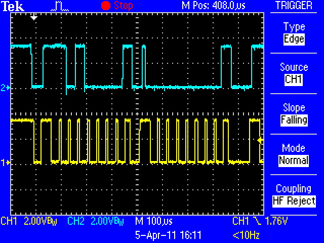
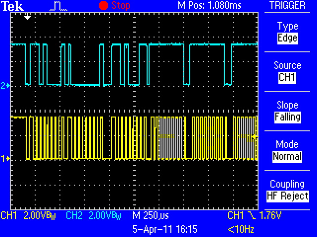
The two scope captures attached show the first two then the first 6 bytes in the burst. Data is on top in blue, clock is below on bottom.
Any ideas - am I missing something really easy here?
Thanks in advance....
Jim-
RTClockData is called about every 5 seconds to load a buffer.
For whatever reason, I'm getting no ack back.
The code is borrowed and slightly modified from Agyeman's EEPROM driver. My confusion is why there is no ack coming back in the 9th clock pulse.
The two scope captures attached show the first two then the first 6 bytes in the burst. Data is on top in blue, clock is below on bottom.
Any ideas - am I missing something really easy here?
Thanks in advance....
Jim-
RTClockData is called about every 5 seconds to load a buffer.
PRI RTClockData | i
  startDataTransfer
  transmitPacket(%1101_0000)    ' Slave Address, write
  transmitPacket(%0000_0000)    ' Sub-Address of starting register

  startDataTransfer             ' do start again per spec
  transmitPacket(%1101_0001)    ' Slave Address again read mode

  Repeat i from 0 to 7    ' Start reading the registers
    RT_Bytes[i] := receivePacket(7-i)    ' get the 8 bytes from the clock

  stopDataTransfer

PRI transmitPacket(value) ' 4 Stack Longs
  value := ((!value) >< 8)

  dira[RTClk]  := 0
  dira[RTDat]  := 0

  repeat 8
    dira[RTDat] := value
    dira[RTClk] := false
    dira[RTClk] := true
    value >>= 1

  dira[RTDat] := false
  dira[RTClk] := false
  result := not(ina[RTDat])
  dira[RTClk] := true
  dira[RTDat] := true

PRI receivePacket(aknowledge) ' 4 Stack Longs

  dira[RTDat] := false

  repeat 8
    result <<= 1
    dira[RTClk] := false
    result |= ina[RTDat]
    dira[RTClk] := true

  dira[RTDat] := (not(not(aknowledge)))
  dira[RTClk] := false
  dira[RTClk] := true
  dira[RTDat] := true

PRI startDataTransfer ' 3 Stack Longs

  outa[RTDat] := false
  outa[RTClk] := false
  dira[RTDat] := true
  dira[RTClk] := true

PRI stopDataTransfer ' 3 Stack Longs

  dira[RTClk] := false
  dira[RTDat] := false
Comments
I knew someone would pick it up quick.
J-
Peeking at your first picture, it looks as if you are not sending a START bit...... or is this picture mid-stream after the start has already been sent ?
Cheers,
Peter (pjv)
According to I2c specs, the Start condition is the falling edge of SLC while holding SDA low. That condition occurs below the trigger marker (down pointing white arrow) on the far left of the screen. I am not aware of a 'start bit' or maybe I'm missunderstanding.
This is the very first communication from the prop about 10 seconds after everyone got powered up.
J-
I think there's a driver by Mike Green in OBEX that has an example of this function...
As I recall, it's just sending a lot of zeros...
This may be the source of the problem, especially since it's one of those "everything but the kitchen sink" efforts (the I2C driver, that is). When learning new parts I always start with simplistic drivers first, just to make sure all the connections are good. If you can get things working with a simple driver, you can certainly get things going with a more sophisticated driver later.
In racing school they used to tell us, "slow in, fast out" when referring to corners. I find the same rule applies to product development.
I don't have that chip but I wrote and attached a really simple demo that I would start with if I did. Note that my driver follows the I2C rules and requires a pull-up on the clock pin.
Thanks Jon!
Here is the final result with the code below.
PRI RTClockData | i RTInit RTstart RTwrite(%1101_0000) ' Slave Address, write RTwrite(%0000_0000) ' Sub-Address of starting register RTstart ' do start again RTwrite(%1101_0001) ' Slave Address again read mode Repeat i from 0 to 7 RT_Bytes[i] := RTread(0) RTstop PRI RTinit | okay '' Define I2C SCL (clock) and SDA (data) pins dira[RTDat] := 0 ' float buss pins dira[RTClk] := 0 PRI RTwait(id) | ackbit,ACK ACK := 0 '' Waits for I2C device to be ready for new command repeat RTstart ackbit := RTwrite(id & $FE) until ackbit == ACK PRI RTstart '' Create I2C start sequence '' -- will wait if I2C buss SDA pin is held low dira[RTDat] := 0 ' float SDA (1) dira[RTClk] := 0 ' float SCL (1) repeat while (ina[RTClk] == 0) ' allow "clock stretching" outa[RTDat] := 0 dira[RTDat] := 1 ' SDA low (0) PRI RTwrite(i2cbyte) | ackbit '' Write byte to I2C buss outa[RTClk] := 0 dira[RTClk] := 1 ' SCL low i2cbyte <<= constant(32-8) ' move msb (bit7) to bit31 repeat 8 ' output eight bits dira[RTDat] := ((i2cbyte <-= 1) ^ 1) ' send msb first dira[RTClk] := 0 ' SCL  (float to p/u) dira[RTClk] := 1 ' SCL  dira[RTDat] := 0 ' relase SDA to read ack bit dira[RTClk] := 0 ' SCL  (float to p/u) ackbit := ina[RTDat] ' read ack bit dira[RTClk] := 1 ' SCL  return (ackbit & 1) PRI RTread(ackbit) | i2cbyte '' Read byte from I2C buss outa[RTClk] := 0 ' prep to write low dira[RTDat] := 0 ' make input for read repeat 8 dira[RTClk] := 0 ' SCL  (float to p/u) i2cbyte := (i2cbyte << 1) | ina[RTDat] ' read the bit dira[RTClk] := 1 ' SCL  dira[RTDat] := !ackbit ' output ack bit dira[RTClk] := 0 ' SCL  (float to p/u) dira[RTClk] := 1 ' SCL  return (i2cbyte & $FF) PRI RTstop '' Create I2C stop sequence outa[RTDat] := 0 dira[RTDat] := 1 ' SDA low dira[RTClk] := 0 ' float SCL repeat while (ina[RTClk] == 0) ' hold for clock stretch dira[RTDat] := 0 ' float SDAIf you look at the data sheet you'll see that the last byte in a multi-byte read gets a NAK, not ACK as you're doing. Here's the fix:
PRI RTClockData | i RTInit RTstart RTwrite(%1101_0000) ' Slave Address, write RTwrite(%0000_0000) ' Sub-Address of starting register RTstart ' do start again RTwrite(%1101_0001) ' Slave Address again read mode repeat i from 0 to 6 RT_Bytes[i] := RTread(0) ' ACK [B] RT_Bytes[7] := RTread(1) ' NAK[/B] RTstopNow your scope shot shows a proper START bit!
Cheers,
Peter (pjv)