

Problems with P2ES_flashloader
 ManAtWork
Posts: 2,330
ManAtWork
Posts: 2,330
I'm currently writing software for my P2 based motion controller board. Everything works fine as long as I load to RAM. I use FlexSpin/C together with the VSC IDE. After loading the compiled code to RAM I get this output in the terminal window:
Executing task: loadp2.exe -b2000000 B2I_main.binary -t
( Entering terminal mode.  Press Ctrl-] or Ctrl-Z to exit. )
Cog0  INIT $0000_0000 $0000_0000 load
Cog0  INIT $0000_0404 $0000_0000 load
Cog1  INIT $0001_D360 $0000_A534 load
lastUpdate = 2216
Cog2  INIT $0002_1E90 $0001_4348 load
`SCOPE Motion SIZE 500 330 SAMPLES 500
`Motion 'NomPos' 0 1_000_000 300 10 15 GREEN
`Motion 'ActPos' 0 1_000_000 300 10 15 RED
Cog3  INIT $0000_0404 $0000_F3B8 load
Cog4  INIT $0000_0404 $0000_A598 load
Cog5  INIT $0002_1A5C $0002_0D40 load
Cog6  INIT $0002_1CFC $0002_0E60 load
WaitNewConnect
However, if I load the exact same software to flash nothing works at all except for the very first two lines of debug output
Executing task: loadp2.exe -b2000000 '@0=P2ES_flashloader.binary,@8000+B2I_main.binary' -t -k
( Entering terminal mode.  Press Ctrl-] or Ctrl-Z to exit. )
P2-ES Flash Programmer
Erasing flash...
Programming...
Done
Cog0  INIT $0000_0000 $0000_0000 load
Cog0  INIT $0000_0404 $0000_0000 load
Sometimes I get some additional lines of garbled characters which might indicate a wrong clock frequency or baud rate. The board has no crystal but instead gets a 50MHz clock from the Ethernet MAC chip. But this is well tested and works on several of my other board designs.
How does the booting from flash ROM really work? I remember that in the early days of the P2 I had to put a clock mode parameter in the command line to make it work. But for my last two projects, the EtherCAT test board and the flight simulator controller, I used the exact same command line and 50MHz clock source and it worked.
IIRC, the bootloader in the internal ROM of the P2 looks for a signal on the serial port. If there's none it tries to boot from flash ROM. It first loads a secondary stage loader that then loads the actual software. The internal bootloader uses RCfast clock and should work regardless of an external crystal or clock. But what does the second stage loader? I hope it doesn't expect a 20MHz crystal. In that case I would end up with >400MHz PLL clock which might work on some boards but only for a very short time before it crashes...
Comments
I don't know if this has changed in a few years. When I was working with the flashloader, the second stage ran at 160MHz and then switched back to RCfast before starting the program. It does a post-divide of 2 so the PLL will be maxed out with 50MHz input, not running at 400MHz as expected.
Here's a simpler flashloader I made to work around issues with some flash chips.
https://forums.parallax.com/discussion/comment/1525737/#Comment_1525737
I have noticed that programs often don't run correctly after programming. So, I always power cycle after flash programming.
If you pass
-SPIto loadp2 instead of explicitly specifying the flash loader, does that work? Don't remember what exactly that does, I think it uses the same thing PNut does?You probably mean -FLASH? So I tried
and it tells me
That might be a power loss on reset issue. Is this an Eval Board you're testing with? I've modified both my Eval Boards now to prevent a tiny brownout occurring with the EEPROM.
What I do is remove R802 and link R801 instead.
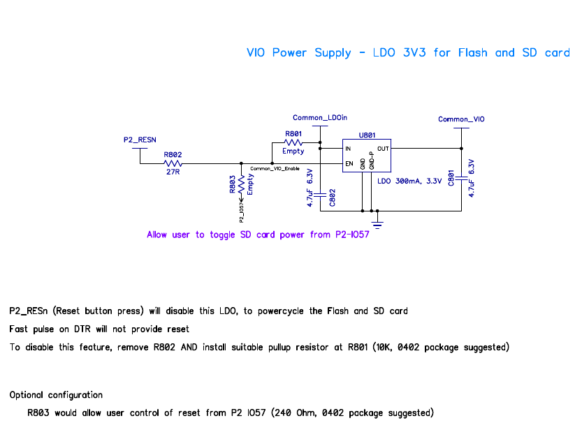
EDIT: PS: The fast pulse, on DTR toggle, is when the brownout occurs.
No, it's this board. +3.3V is powered from an 800mA LDO which is enabled all the time. I use a special isolated ProgPlug so I'm pretty sure there are no glitches caused by the DTR pulse. But the reset signal also goes to the Ethernet chip and could cause the oscillator to stop. That shouldn't do any harm if the bootloader is independant of the external clock and uses RCfast. But that's just my assumption which might not be true.
The other board from 2023 uses the exact same Ethernet chip and clock circuit. But I just noticed it had a ZD25W016 flash chip. The new board has an IS25LP080. I thought I have successfully tested it but I have to double check... The P2 is a bit picky and maybe doesn't like all of them.
Edit: verified, I've tested the IS25LP080, at least with the KISS board.
Feeling like it would be nice to have a single stage flash bootloader for troubleshooting that just works off of RCFast...
Loadp2 does. I just checked the sources. Both options, -FLASH and -HIMEM uses RCFAST for both programming and loading. Looks to be now based off of Chip's
flash_loader.spin2reference code which was the first to use RCFAST.So the XI frequency won't have any impact on EEPROM burn or boot.
PS: I'm using Loadp2 v0.077 - https://github.com/totalspectrum/loadp2
Looks like you have to specify "-SINGLE" for loadp2 to just use RCFast (looks like anyway):
https://github.com/totalspectrum/loadp2
Yeah, maybe need both -SINGLE and -FLASH together. I haven't actually read enough to know how -FLASH integrates.
Well, maybe that doesn’t actually specify the loader that gets written to flash?
Still thinking we need ground zero tools for troubleshooting …
-FLASH provides both the burner and the loader. As already mentioned, they're both based on Chip's
flash_loader.spin2reference code.When using -SINGLE there is no diagnostics but when using default -CHIP along with -FLASH and -v for verbose Loadp2 reports this on success:
To me that looks like four operations.
1: 'S' for loading the fast loader.
2: 'S' for loading the payload to be burned to EEPROM.
3: 'K' for burning the EEPROM.
4: 'F' for launching the payload on the Prop2.