

Electromagnets! E-LEC-TRO-MAG-NETS!!
 mpark
Posts: 1,336
mpark
Posts: 1,336
(IDK, I just like that word ![]() )
)
So I bought this 5V electromagnet, and I have a couple of questions.
That product is described as having "25kg holding force"[1] which makes it sound like the magnet should be able to lift a 25kg weight, but noooooo: the description emphasizes "This is not how much weight they can pick up!"
OK, fine. First question: What the heck is holding force, then??
Anyway, I don't actually need to lift 25kg, so I got the magnet and it turns out to be a little weak for my purposes at 5V, but if I bump up the voltage to 12V, it's plenty strong. BUT then it gets hot. Which I get. I was hoping it wouldn't be a problem with the low duty cycle I'm using but over time it definitely warms up.
So now I'm looking for a 12V electromagnet, but I don't know what holding force to look for. My second question: What is the holding force of a 5V electromagnet with 25kg holding force when 12V is applied?
Or maybe there's some better way to ask how to select a 12V electromagnet that will behave like my overdriven 5V electromagnet.
Of course this all assumes the 12V model won't get so hot, so LMK if that assumption is incorrect!
[1] We'll just ignore the fact that kg is not a unit of force
Comments
Having said all that, I just realized that once I know the holding force of an overvolted 5V electromagnet, I could presumably just get a 5V electromagnet with that higher holding force. That would simplify things by eliminating the need for a 12V supply.
If they say it has a holding force of 25kg then it should be able to hold a weight of 25kg when 5V is applied. However, it is absolutely mandatory that the plate that closes the magnetic circuit is of pure iron, is thick enough (4-5mm at least) and the surface is perfectly even and it covers the whole surface of the magnet. The smallest gap, paint or dust on the surface makes a huge difference. A gap of 0.5mm can reduce the holding force down to 5kg or less. An uneven object like the wrench shown in the picture doesn't work very well.
Off topic, but just for fun...
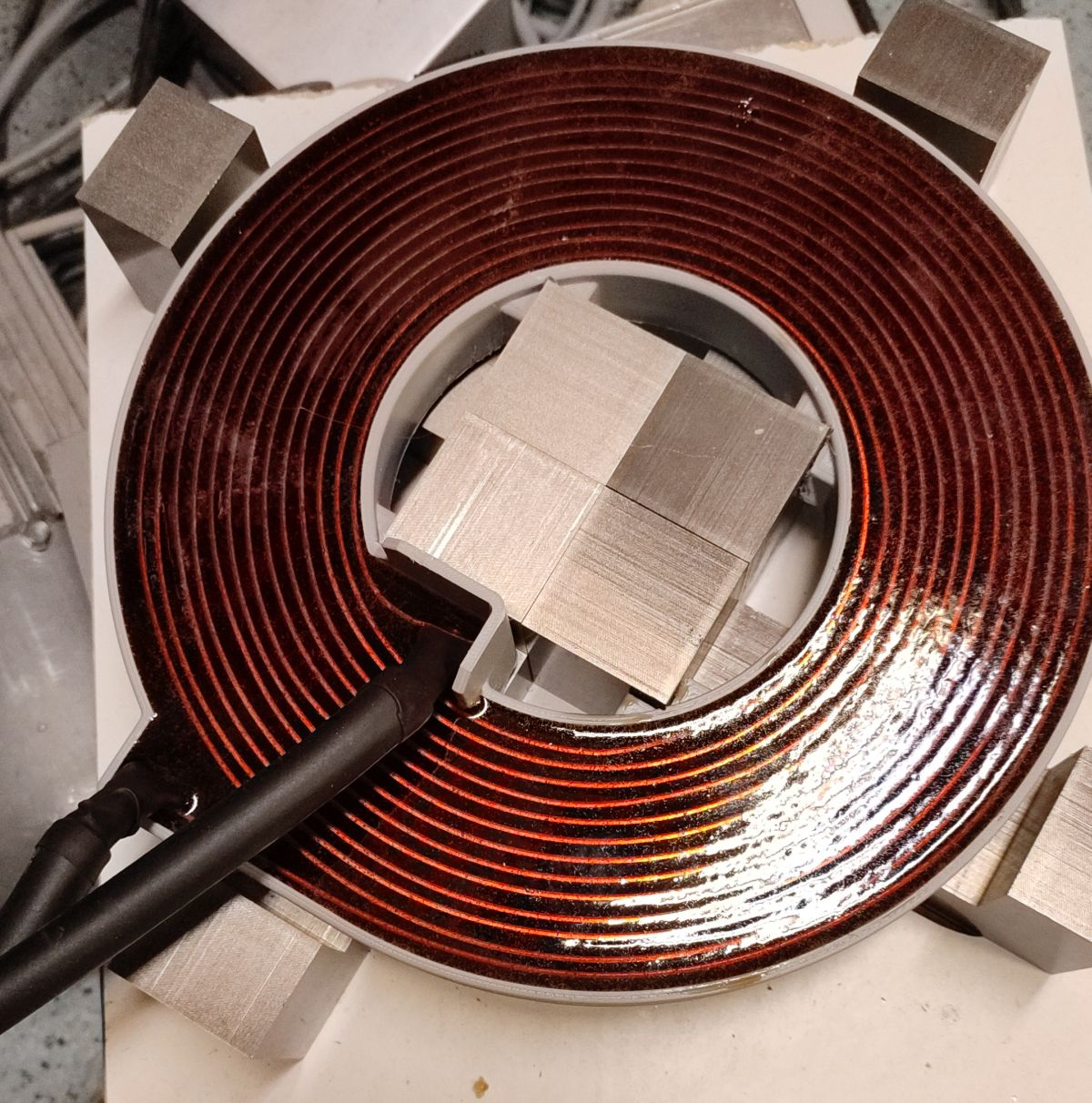

This is an electromagnet I made recently. It's designed to produce a magnetic field of 1T for short pulses of 300µs with 1400V and 1400A peak.
...
Good grief. Those numbers sound terrifying, but I can't get a sense of how big that thing is. Needs a banana for scale.
Also, thanks for the explanation of holding force.
Sorry, I have no banana. An orange is OK?
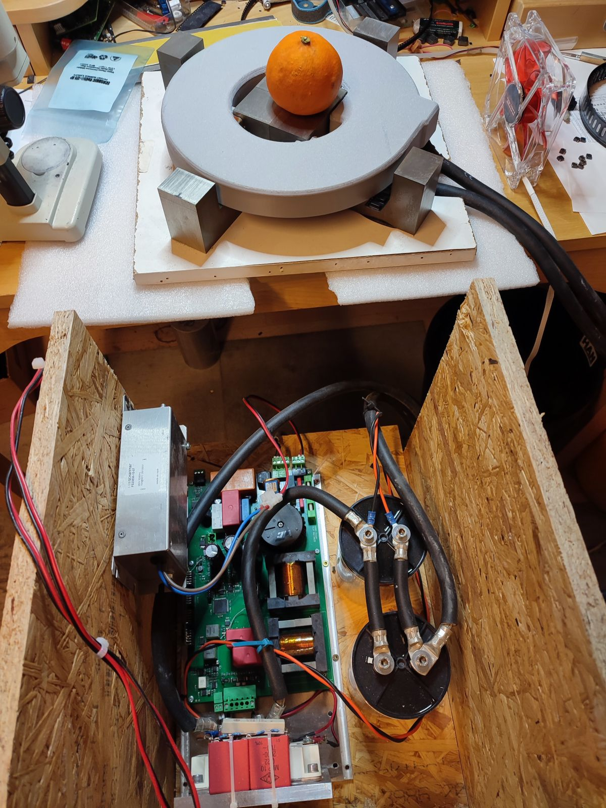
The PCB at the bottom is the power supply and two big caps for energy storage.
Are those pole pieces Ferrite? I know nothing about the math of this, but I would be afraid they'd snap..
Looks like the coil is made of a ribbon. Cool Project!
The four U-shaped pole pieces below the orange are made from stacked sheet iron. The coil is made from copper ribbon.
The two double-E cores on the PCB are ferrite.
Sorry for hijacking the thread... @mpark How much holding force do you get at 5V and at 12V?
Ha, no worries! Holding force is a tough question 'cuz I'm not using the EM to really hold anything. My application is more like a primitive linear motor. At 5V my EM didn't have enough oomph, at 12V it did. Very scientific.
But as the EM heats up, I think less current flows and the magnet loses a bit of oomph, enough to mess up my system. That's my suspicion anyway, but there are many other possible explanations for my system mess-ups (though I have ruled out the cat).
I see some stronger 12V electromagnets but they're a bit bigger than the one I have and I'd prefer not to have to re-3D-print this setup (yes, I'm so lazy that even having a machine do the work for me is too much work).
I ordered a little heat sink to attach to the electromagnet. We'll see if that keeps the temperature down and the oomph up.
Those "pot core" electromagnets are rally only good for holding. The force gets exponentially weaker with increasing air gap. The other type of electromagnets which look like a relyy coil with a cylindical pole inside the coil is much better at providing force over a wider travel range.
How much force and how much distance do you need?
Good to know, thanks! Got any good sources to recommend? I'm not having a lot of luck googling.
As the wire heats up, the resistance of the winding increases. If you're using a constant voltage to drive it, yes the current and power are going to drop
Damn! Have you actually measured that performance? Only two caps delivering 1400A ... that's gotta be 50x the ripple rating of the caps!
A pulse width of 300µs with a repeat rate of 50Hz means the duty cycle is only 1.5%. 1400A peak is only ~1000A RMS and multiplid with sqrt(1.5%) that gives a total of 121A RMS averaged over time. Each cap is rated for 100A RMS or 5.6kA peak so it should be fine.
I cannot measure the current but I can measure the voltage, inductance and capacity. The voltage waveform at the caps and the L and C values match my simulations so I assume the current should also.
Jeepers, I've never tried to do the maths so extreme. Is treating it as a long average really correct? ESR is going to play a big part here.
I'm not worried about the capacitors. They don't get warm. ESR is around 2mR for each cap, 3.5mR for the coil and 1.5mR for the cables. So with two caps parallel it sums up to 6mR (milliohms). So the resistive loss at 1000A is around 6kW but only for 300µs. The stored energy at 1400V is 50J and the resistive loss per pulse is 1.8J. So theoretically the "efficiency" (energy pay back vs. loss) should be better than 96%. At 50Hz pulse frequency the resistive loss is 90W. But the actual power consumption is around 400W. The rest of 310W are losses in the switch (IGBTs) and eddy current losses in the coil and the core.
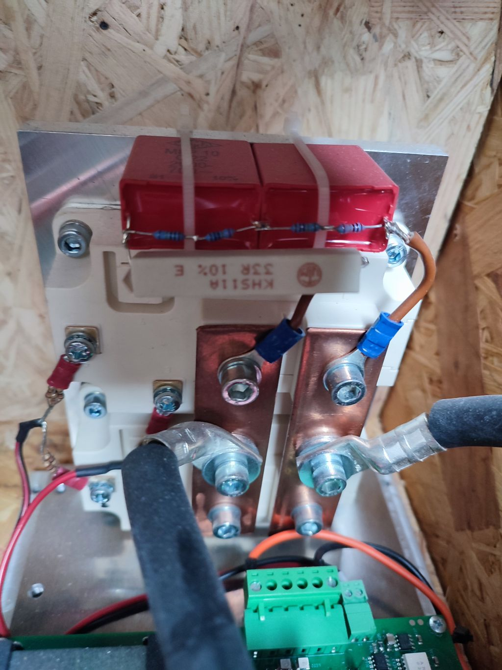
I haven't found a single power semiconductor capable of switching 1400A. Well, there are thyristors that can do that but they come in a "hockey puck" case which is very difficult to handle. Insulation and cooling result in mutually exclusive requirements. So I decided to use two parallel wired IGBTs instead each capable of switching 600A continous and 1200A peak. Paths with exactly the same resistance for both IGBTs is essential, here. A difference of only 0.1mR would mean a voltage difference of 1.4V. This would be enough for one of the IGBTs having to carry almost all of the current and the other almost none.
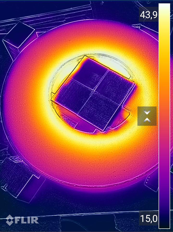
However, the majority of the heating happens in the coil. It's interesting that the inner windings get hotter than the outer ones. But that's no surprise as the inner windings are inside the magnetic field of the outer windings but not vice versa.
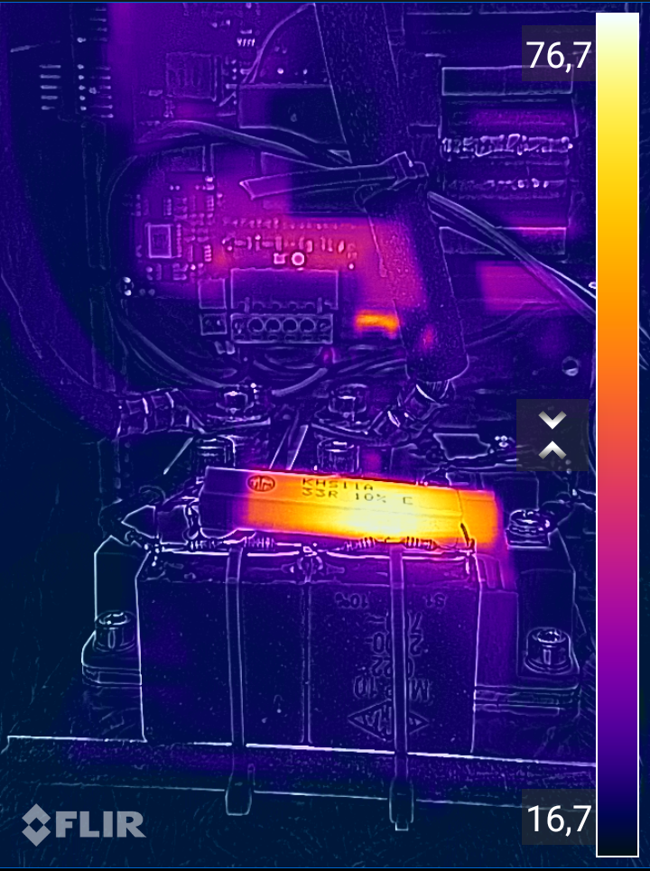
The iron core stays cold. Also, the IGBTs get barely warm. The resistor of the protection snubber network gets fairly hot (~76°C, ~10W). It has to swallow the peak caused by the reverse recovery current of the body diodes of the IGBTs.
I was thinking more about calculating peak current. But it seems my knowledge there is lacking. The inductive properties obvious matter far more than resistances.
You don't have to worry too much there. I've read that IGBTs are happy to be paralleled, same as FETs. I presume the reason is the same: They exhibit a positive temperature coefficient for the fully-on resistance, same as FETs. Presumably because there is a FET structure in the IGBT.
Paralleling for high current is probably what everyone does.