

Conversion of a Sewing Machine as an Embroidery Machine controlled by P2
 Christof Eb.
Posts: 1,548
Christof Eb.
Posts: 1,548
So let me put together an overview for my P2- controlled embroidery machine. Perhaps it might be inspiring for someone...
The first picture shows how the work is distributed between 4 cores of P2 . I think, this is a nice project for P2, because vertical movement of the needle and lateral movement of the frame are done partly in parallel and at least the AC triac control for the sewing motor is time critical.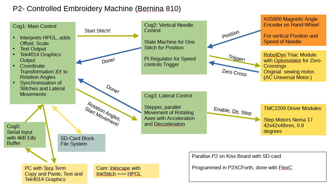
I wondered, if the movement of the frame could be done with two rotating axes instead of orthogonal movement. The 2 wheels are printed from ABS. So I did not need to buy many parts. And don't we want to have some innovation?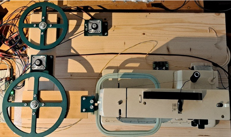
This sketch shows the coordinate transformation from XY to the two angles. The needle sits at 240,240 and shall penetrate the fabric at local coordinates 50,75. This is achieved with the angles 19,1342° and 64,229°. You could argue, that the transformation is "quite natural for P2" because it has a Cordic solver to do rotations.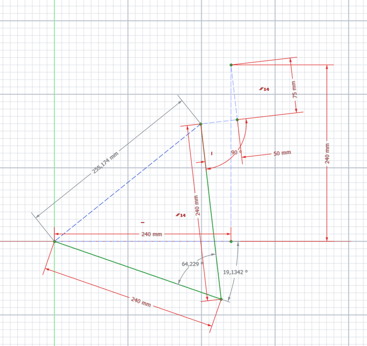
The controller must have a sensor for the vertical position of the needle. Here we use a AS5600 Magnetic Angle Encoder at the Hand Wheel of the sewing machine. The same sensor signal is also used for the underlying control of the motor speed. The sewing machine has to be tamed very much, which is done with a triac phase controller, a "RobotDyn" module.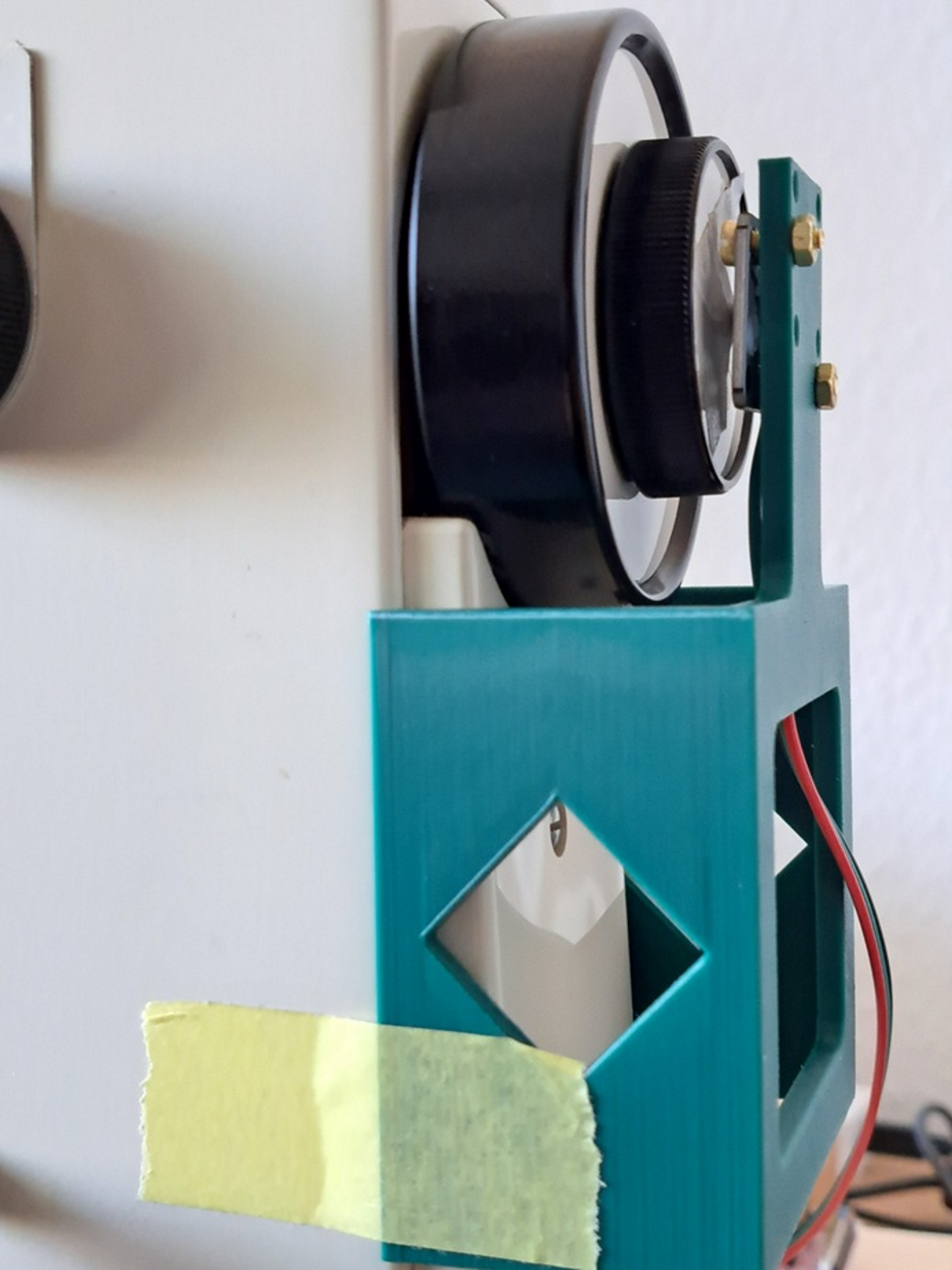
Synchronisation of needle movement and lateral movement is done like this:
A cycle (0...255) starts with zero, when the needle enters the fabric.
After it has left the fabric at 135 the lateral movement of the stepper motors can begin. As soon as it is completed a new new stitch may be scheduled.
If no new stitch is pending, the needle motor will stop at 180.
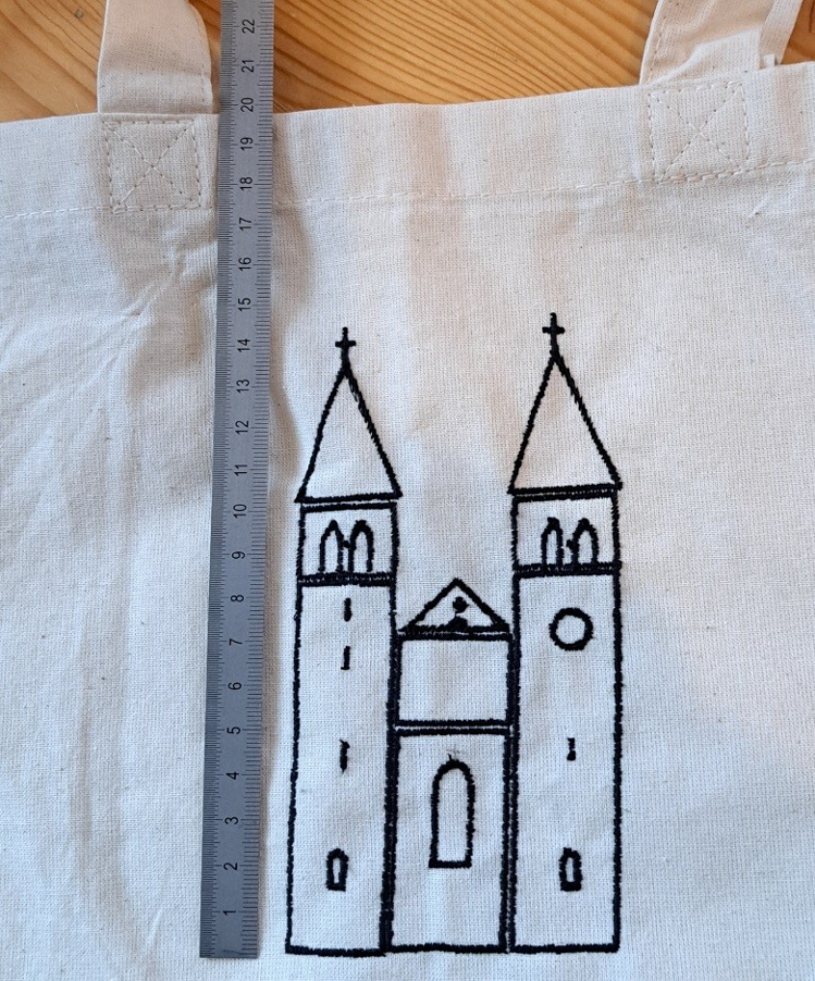
An example: Saint Peter and Paul, a nearly 1000 years old church at the Lake of Konstanz.
https://de.wikipedia.org/wiki/St.Peter_und_Paul(Reichenau-Niederzell)
About 5600 stitches as "satin columns" using a 75 embroidery needle and 402 polyester yarn on a cotton bag.
If you don't want to program each stitch, you will like to have some CAM chain . Here I was happy to find InkStitch https://inkstitch.org/docs/workflow/, which uses InkScape as a drawing program. You can then convert lines and filled areas to stitch patterns and check the result. Finally you can output some file with data for each stitch. I choose HPGL as file format because it uses integer cordinates and the interpreter is very simple.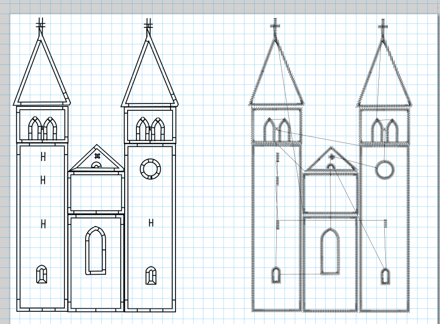
This project came after I did some experiments writing my own Forth compiler using the XBYTE mechanism of P2. So it was quite natural to try to do the project with this. I like to do use Forth, because it is fast for an interpreter. And it is so compact that you don't have to worry about external RAM. You can try out things very easily often without need to write special test code. The interpreter gives directly the user interface in the PC terminal window. I use a local Editor so edit-compile-run is a matter of seconds as you normally only need to recompile a smaller part.
I had given insights to the progress (and hard times) of the project here: https://forums.parallax.com/discussion/176269/towards-a-p2-controlled-embroidery-machine/p1
Special thanks go to the nice and helpful Forum members!!! Creation of P2, making it usable with the Kiss board, and the FlexC Compiler!!!
Have Fun Christof
Comments
Perhaps some more detailed information might be interesting:
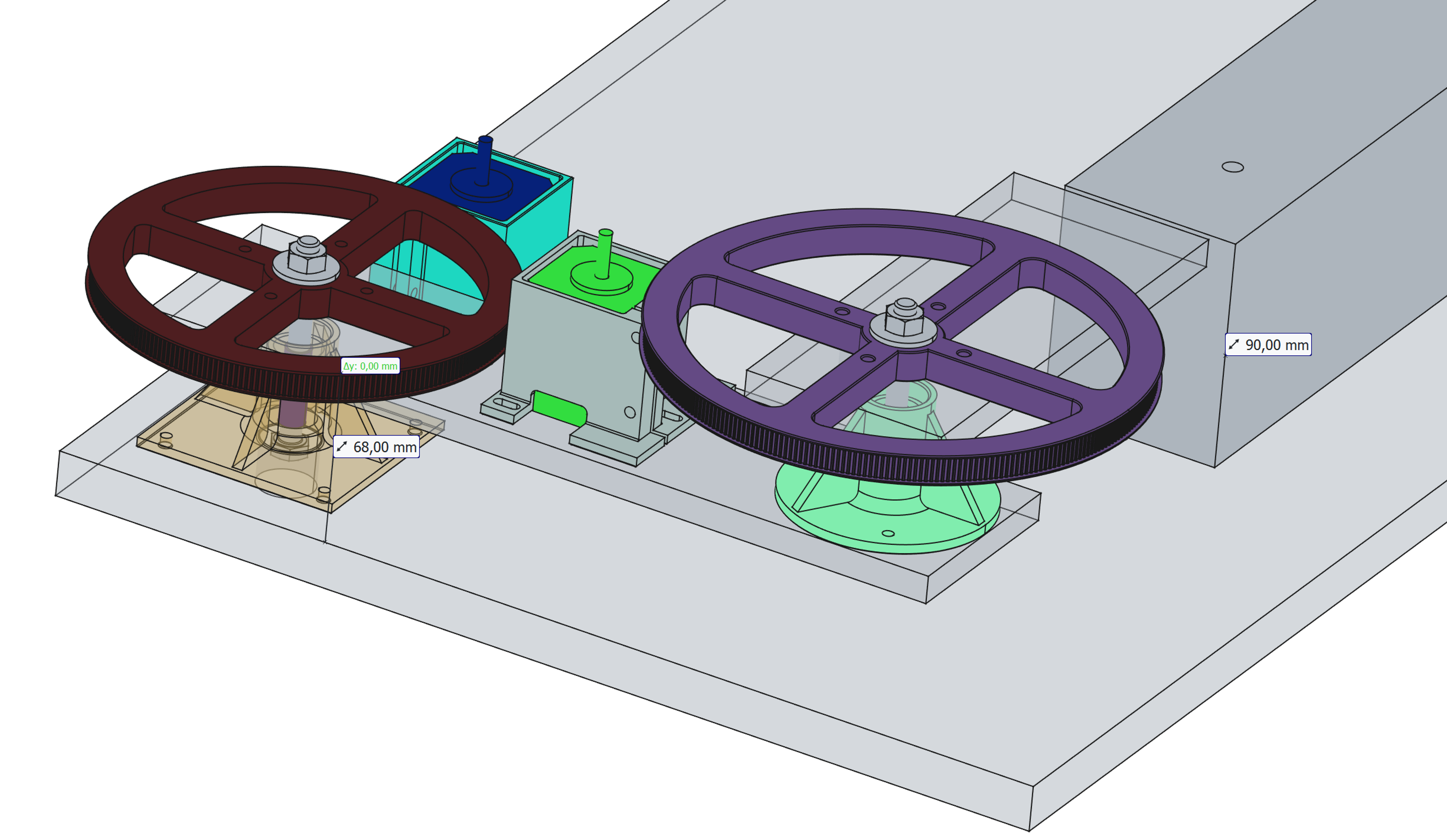
Mechanics for the Movement of the Frame
Step motors: https://omc-stepperonline.com/de/nema-17-bipolar-0-9-grad-44ncm-62-3oz-in-1-68a-2-8v-42x42x47mm-4-draehte-17hm19-1684s
Tooth Belt drive:
GT2 with width 6mm and length 610mm. 16 and 240 teeth at shoulder. 16 and 288 teeth at elbow. Diameter of smaller wheel is 2402/pi=152,79mm
Length of belt per half-step is: 16pi/400/2=0,0628mm
So resolution for half-step at radius 240mm is: 240/(2402/pi/2)16*pi/400/2=0,197mm. We actually use microstepping but as stiffness drops for the microsteps, they do not help too much to increase accuracy.
The wheels have been made using the "gear" workbench of FreeCad as timing gear. Print with ABS material. I was astonished, that the print fitted to the belt first time.
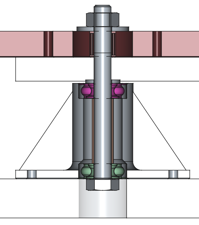
The design of the bearing units is similar to the bearing of a motor cycle rear wheel. Two ball bearings 608ZZ 8x22x7mm are used. They have a press fit in the bearing chair at their outer diameter D.design=21,9mm. At the inner diameter they have a looser fit on the axle. Partly I used some adhesive tape "to shim" the diameter. The axle is a bolt M8x80 and the bearings are held apart with a sleeve, so a nut can be tightened to press the parts together on the axle. So the bearings have no play on the axle. You can feel no play in the setup.
Controlling the Motor of the sewing Machine
This part was the most difficult of the project. The motor has to be throttled and wants to speed up very much. During one stitch cycle the load torque varies very much. Also at starting friction is high. So you have to regulate power during one stitch.
The motor of this sewing machine is an AC universal motor with field winding in series to the rotor. The original starter pedal consists of resistors in series to the motor. This pedal is clamped to 0 ohms.
I first tried simply switching on and off the motor with a solid state relay. This approach was far too slow.
Finally I ended up with a RobotDyn Dimmer Module, which meant, that P2 has to generate trigger pulses for a triac. This module also generates a zero-cross signal.
The sewing machine has a light bulb. As the dimmer module sits before the mains plug of the machine, it also dims this bulb. Regulation works best, if the light bulb is switched on.
Motor control software runs in it's own cog and has three levels:
1. A state machine on highest level, which does one single stitch after being triggered and watches the position of the needle. It outputs a target-speed.
2. A PI regulator controller for the speed of the needle. (Or better the hand-wheel of the machine) It outputs a phase angle as a power requirement.
3. A state machine for the phase angle, which outputs a trigger pulse for the triac a certain time after the zero-cross signal. The earlier the trigger pulse is fired, the longer the triac is in on-state. This lowest level uses a smart pin PWM signal described here: https://forums.parallax.com/discussion/177786/controlling-an-ac-dimmer-circuit-via-smartpin-pwm#latest
As the motor is running slow for a long time, it needs an external fan 50x50x15mm at the venting slits.
Coordinate Transformation
While we need two angles or numbers of steps, we have given local XY coordinates within the frame. It took me some time to come to a simple solution of the task: Let the Cordic Machine of P2 do the work.
With it's "rotate" command it is easy to rotate a XY pair by an angle. So we can first rotate X,Y by the elbow-angle and then by the shoulder-angle. This is a conversion of given angles and XY.local to XY.absolute. But we need the other direction. To achieve this, we use something like a 2-dimensional successive approximation.
For each approximation step for both shoulder-angle and elbow-angle a delta-angle is either added or subtracted, if this gets us nearer to the destination. Then the delta-angle is multiplied by factor 0.9. This is done in a loop which ends if either the distance to the destination is under a limit or the delta-angle is under a limit.
Starting values of the angles and the delta-angle are choosen in a way that only the right of the two possible solutions is found and also the number of iterations is not too long.
The iterative seeking is done while the machine is busy with the needle in the fabric, we anyways have to wait for lateral movement until the needle has left the fabric.
Easy to read diagram. And great result too - especially considering the home made construction of the x/y slides. They must be a snug fit.
Wonder how well it does with satin stitching (?) filled shapes...
Those funny plush dolls I collect have their eyes done like that and it basically requires machine precision to look good (can't grab a good closeup pic right now).
Might be interesting to have a CheapTM embroidery conversion kit that can do stuff like that, might find a few customers in those sorts of circles, there's a lot people making custom ones in that/similar styles.
Hi,
what is the size of this eye? For example the length in mm of the horizontal line on top? About 8mm?
(This type of eye I found here: https://www.reddit.com/r/Inkstitch/comments/1dn8rld/inkstitch_not_completely_filling_the_infill/ The link shows, how the eye is designed with Inkscape. Unfortunately no scale there.)
I am not sure, where most of the jitter of the stitches comes from.
Friction and deflection will play a role.
I think I got an improvement, when I used a new (sharp) needle.
I also wonder, what influence the cloth has. The resolution of the stitching is higher than the structure of the fabric. I am not sure, if the needle slips aside from a yarn of the fabric, or if it goes always through. The fabrics I used have been old linen bedclothes and these cotton bags. Both materials are not very elastic. So I did not use any stabiliser. Stabilisers are a great mystery for me at the moment. (If you try to find definite advice, you're told that you must try it out....)
The switch from 1.8 degrees stepper motors to 0.9 degrees did not bring such great improvement, but I have not done a real comparison.
I have reduced the density of stitches from 0,4mm to 0,6mm (peak to peak of zig-zag) for the example to have less stitches. Probably higher density looks better.
I can try something with a filled shape. Must ask for some fine but inelastic fabric.
What I can say is, that the machine as is can do much better precision, than I can do by hand.
As I wanted to bring some embroidery onto those shopping bags, I was aiming at a "big" working area. The inner size of the frame used for the example is 165x145mm.
The armes of the mechanics could be made shorter for smaller area resulting in higher precision.
I think the horizontal bar is about 37mm across (for a 20cm standard-size doll), but that's guesstimated (still not back home). They're not 100% consistent between manufacturing runs (and of course different characters may have the more arched top, the more flat top, some have a little hook eyelash thing,, etc)
A coarse kind of fabric like what bags are made of I think will inherently lower the resolution, yeah.