@rogloh said:
... But I think the NCO Duty mode from the P2 sounded cleaner than sawtooth PWM - although to be fair I'd limited that to 8 bits to be as close to what the RasPi puts out as I could match in the SNECog demo. The NCO duty mode probably adds a few more bits of resolution at a P2 clock of 200MHz.
Assuming the DAC accepts it, PDM is even noise across all amplitudes/ratios. The noise is pushed right up into its highest resolution switching in the MHz.
PWM has its worst noise at the 50% ratio - ie: zero crossing, low amplitudes. Exactly where it will be most audible.
PWM makes sense where switching losses are more important than audible noise. Power supplies and electric motors being the poster boys.
I do wonder how class D audio amps are designed. Do they use the digital data directly? Or they are all still designed to use a analogue line in? I've never looked ... I suppose that's what's going on with the wireless speakers, they take digital audio and directly modulate that without any analogue stages at all. So the real selling point is not the wirelessness at all (Since the power wires are still needed anyway), it's the direct modulation.
Awful photo but here's the LCD working with my hacked up video driver doing parallel output. In the end it is a little fussy about its timing. If I start messing with the back porch or hsync widths it seems to offset the picture on the screen, also different vertical back porches offsets it down. You can vary the front porches though and it is okay with that.
I found the LCD screen does work all the way from 20MHz to 340MHz P2 clock frequencies I tested (at different refresh rates). I do see a little corruption of text on white backgrounds, not sure if it is a signal integrity type of issue or something else...still tweaking, and the clock alignment might not always be centered - things do change if I add some nops to the startup code.
@rogloh said:
Awful photo but here's the LCD working with my hacked up video driver doing parallel output. In the end it is a little fussy about its timing. If I start messing with the back porch or hsync widths it seems to offset the picture on the screen, also different vertical back porches offsets it down. You can vary the front porches though and it is okay with that.
That's what happens when you omit the DE signal.
Unrelatedly, tried my code? (see prev. page) I haven't been able to scope it yet, but it should at least generate a clock and some signals.
@rogloh said:
Awful photo but here's the LCD working with my hacked up video driver doing parallel output. In the end it is a little fussy about its timing. If I start messing with the back porch or hsync widths it seems to offset the picture on the screen, also different vertical back porches offsets it down. You can vary the front porches though and it is okay with that.
That's what happens when you omit the DE signal.
Yeah I will try to add the DE signal back in to see if it changes much there when the back porch widths are modified. I've also modified my driver code for parallel LCD output such that H & V syncs now both come from the bits in the immediate streamer data during blanking so the extra DE signal is going to be very simple to add. As the LCD seems to use negative syncs I do need to invert the sync output pins in the pin configuration mode with a wrpin because you can't easily control the state of the lower 8 control bits during active video output (both are always outputting a 0 there, automatically by the P2 HW).
Unrelatedly, tried my code? (see prev. page) I haven't been able to scope it yet, but it should at least generate a clock and some signals.
Nice. We may have to invert the video output RGB data pins for some weird reason. I'm still looking into it but the colours seen were sort of the complements of what I expected, but I could have a bug somewhere there, so not 100% confident on that yet.
UPDATE: Actually I misread your comment above. No I haven't looked at that yet, still getting the LCD image perfected so I know what the issues are.
@Wuerfel_21 I grabbed your lcd24-test branch build and configured it. Was very close but no cigar. To get something to display I just had to hack the NeoVGA code to invert the 3 control bits DE/HS/VS (DE=1 means data is valid, plus this device only wants negative syncs). But it was still offset on the screen with the default timing - not sure why DE is not fixing that. I tweaked it to use the RasPi timing I found and got a valid-ish bootup screen (apart from the right edge and pixel shimmer which might be clock phase or sync timing related).
After loading a game the video looked better but the sound was rather messed up. Heard a loud buzzing sound and only faint real music/gameplay sounds - maybe audio offsets/math is wrong for NCO mode or that hasn't been looked at yet?
UPDATE: ok I see you have not enabled NCO mode - will try to modify that in your code to see if it helps...
I sort of wonder if usbnew might still be messing with the USB base pins somehow given that the PWM pins are at 32,33 while D+/D- are on 34, 35 and I did also see that random garbage was being read into the USB keyboard buffer in your hidpad_to_vga test app if SNECog audio is playing while this test program is running. It's like there is data pin crossover or leakage somewhere between audio and USB. I wonder if that old USB repo pin is getting enabled or something?
In my own p2videodrv code I've added a clock pin sync up hack to lock the transitions of the clock signal to some fixed phase offset from the RGB pixel data transitions and the corruption problem I saw earlier with white backgrounds is also resolved (which was my own bug). Text is very crisp now and I need a magnifying glass to see the pixels - they are tiny. I think the LCD is stable when fed a stable source. I just would like to be able to modify the timing more without the window floating around when the back porch is varied, I was sort of hoping DE would fix that. At one time I thought it had as I could freely modify the timing parameters, but I can't reproduce it again and am wondering if I was even modifying the correct driver file in the same folder or some other file elsewhere now.
I also recently noticed separately that audio buzz when the USB is on if the PWM GPIO pins 32 & 33 are left floating. I now just drive it with a zero until some valid audio is started and the buzz is reduced. Got to find the source of it. Didn't hear it initially while first trying getting any sound to work.
@Wuerfel_21 I got sound working on your NeoYume - hides most of the buzz now but doesn't fully eliminate it. You can see my major hacks here in the zipped archive of changed files:
I do see occasional screen corruption in game which could be an artefact of heavily reducing the blanking and it doesn't always get the timing right at the startup - so there is probably random clock phase there. Might be able to pad more into hsync front porch. It seems to want the hsync and back porch widths as is though, plus vsync and vbp timing or it will offset the screen.
I've noticed if I download a new version via the PropPlug which involves a P2 reset I also need to power cycle the system then too or I get a failure to read the SD card. That's a bit of a PITA and would be nice if fixable somehow. Perhaps final SD or flash boot may behave differently...?
It's actually a fun little system to play games on. Screen looks so crisp when working right.
@rogloh said:
I do see occasional screen corruption in game which could be an artefact of heavily reducing the blanking and it doesn't always get the timing right at the startup - so there is probably random clock phase there. Might be able to pad more into hsync front porch. It seems to want the hsync and back porch widths as is though, plus vsync and vbp timing or it will offset the screen.
You can not and should not mess with the vertical timing. When changing horizontal timing, you should keep the total number of cycles the same, otherwise the whole timing will be too fast or slow.
You can also try loading the 240p test suite ROM to get some test patterns. (make sure you go to the options and set the full 320 width mode)
I've noticed if I download a new version via the PropPlug which involves a P2 reset I also need to power cycle the system then too or I get a failure to read the SD card. That's a bit of a PITA and would be nice if fixable somehow. Perhaps final SD or flash boot may behave differently...?
There's some SD cards that do this for unknown reasons, try a different one.
@rogloh
Okay, so that that timing modification works at all is a miracle, it's totally bogus. You're changing the total scanline count (NEVER DO THIS) and also everything would be running way too fast, 70Hz roundabout. (The correct speed is 59.599 Hz - notably slightly slower than the NTSC standard 59.98). This is also probably causing glitches, since the 68k code now has almost no VBlank time to work with and the Blitter code was marginally handling worst-case lines to begin with.
Basically, don't ever attempt to change the total number of cycles, you can only move them around. E.g. if it doesn't care about front porches, you can move the extra cycles/lines there and be hopefully unbothered about it.
@Wuerfel_21 said:
Okay, so that that timing modification works at all is a miracle, it's totally bogus.
Yeah I know, major hacks is what I'd mentioned. I'd like us to be able to preserve your timing but unless the DE thing can be resolved I think it will need to be reallocated across front porches for vertical and horizontal to avoid visible offsets on screen. I'll adjust it here and retest to see if that glitchiness goes away. BTW the menu screen at the starts seems more prone to problems in the pixel clock sync than the gameplay.
Um, yeah I hadn't changed your setting for the clock yet - I believe I've set my driver to to an inverted output, but I also adjusted via a waitx to try to center it which may have altered it again.
EDIT : Also you used sync_io and I didn't set that yet. It makes more sense to align to latch the clock in the P2.
Yes that helps by inverting the clock. Pixels in MS game are spot on now. No bad glitching anymore with the timing change I made too.
There is still some visible corruption however in the initial menu on the right. Almost seems like the timing for that screen is different to the game play?
I'll also try scaling back the audio sample values by a bit or two, maybe I'm just overdriving the on board amp...
EDIT: Also the background buzz seems louder when I see that corruption. Perhaps I need to adjust slew rate of the PWM output pins by adding a internal resistor drive level or use the bitDAC.
All video tests looked absolutely spot on (to me at least) if the main menu was stable initially. If not then it was also corrupted down the right side in the tests with flickering garbage near the end of some lines.
Something can get this thing into a bad state from startup and then it's hit or miss after that. But if it starts up cleanly it's nice.
When I get a chance (perhaps tomorrow) I'll try to record the audio output from the 240p audio tests and attach a zipped wave file or something. You'll hear some weird audio tailoff effects at the end of the notes of the FM synth tests and then the residual buzz. Also L+R channels are flipped according to real headphones and the internal speaker output is mono.
@rogloh said:
All video tests looked absolutely spot on (to me at least) if the main menu was stable initially. If not then it was also corrupted down the right side in the tests with flickering garbage near the end of some lines.
Something can get this thing into a bad state from startup and then it's hit or miss after that. But if it starts up cleanly it's nice.
I suppose you can't scope out the signals for when this is happening vs not happening?
Do you think this is the driver or the LCD controller getting into a bad state?
Also, what timing are you setting now? (I think setting any of the horizontal timings to super-low values like you had is highly problematic and might indeed cause some weird timing misalignment where the streamer runs out of commands)
When I get a chance (perhaps tomorrow) I'll try to record the audio output from the 240p audio tests and attach a zipped wave file or something. You'll hear some weird audio tailoff effects at the end of the notes of the FM synth tests and then the residual buzz. Also L+R channels are flipped according to real headphones and the internal speaker output is mono.
I didn't look at the audio part at all yet - it's all a bit tricky with OPNxcog; OPN2cog I think was my first big P2ASM project, so it's kindof a mess and that carries through to the OPNBcog in NeoYume (that, if you ever thought about that, doesn't exist as a standalone lib because it's hard-tied to the NeoYume memory arbiter).
Getting weird trails from low-amplitude-but-not-quite-zero signals from NCO_DUTY mode is just how that is, a similar problem happens on P1 (where this is the default / only acceptable way to produce audio).
One thing I'm thinking is that maybe the low-pass filter doesn't quite return to zero in all cases (i.e. gets stuck at -1 instead of returning to 0) due to rounding and that's what can cause duty mode problems. (unrelatedly, also try setting P_SYNC_IO on this).
For testing you can just bypass it (mov opn_arg1, opn_outl directly etc), but it will sound too harsh (or maybe not - if the filtering applied to the PWM signal is too aggressive disabling the software filter might cancel that out)
Currently the delta applied to the filter values is rounded down (because it's using SCAS, which is essentially MULS+SAR), so it can get stuck just below zero. I think to fix it I need to change it to round away from zero. I think this is possible without adding any instructions...
To fix the left/right issue, just change the config (duh).
@Wuerfel_21 said:
I suppose you can't scope out the signals for when this is happening vs not happening?
It's difficult to probe inside the case - although on the back I can probe the upper signals on the P2 Edge connector (which is all the P2 IO pins to P37). I can't easily see the screen at the same time as probing though. Maybe I can get a mirror or something to help that.
Do you think this is the driver or the LCD controller getting into a bad state?
Not sure yet, it might be some initialization timing. Maybe the pixel clock only needs to start after syncs/DE and data pins are valid or something. I'd expect the P2 and RasPi to be pretty quick to power up the video when booting up from 5V turning on, but if I load serially there will be a delay. With any luck the microcontroller that powers up inside this thing would wait to turn on the LCD after it sees syncs, but IDK. I still want to know why the DE seems ignored and am looking more into that too.
Also, what timing are you setting now? (I think setting any of the horizontal timings to super-low values like you had is highly problematic and might indeed cause some weird timing misalignment where the streamer runs out of commands)
Timing is this for now (total pixels and lines is the same, but is shifted to put most blanking in the front porches):
timing_lcd24_640x480
long VIDEO_CLKFREQ  ' CLKFREQ
long 2              ' active line multiplier
long 12+1+32          ' V front porch
long 1 '2              ' V sync
long 2 ' 34             ' V back porch
long 0              ' extra pillar
long 640            ' blank line
long 16+55+36             ' H front porch
long 1'56             ' H sync
long 20 '56             ' H back porch
long $0924924a      ' Sync NCO
long $0924924a>>1   ' Pixel NCO
long 0              ' Alt-res NCO
long 14 + (14>>1)<<16 ' pixel clock pulses
long 1
When I get a chance (perhaps tomorrow) I'll try to record the audio output from the 240p audio tests and attach a zipped wave file or something. You'll hear some weird audio tailoff effects at the end of the notes of the FM synth tests and then the residual buzz. Also L+R channels are flipped according to real headphones and the internal speaker output is mono.
I didn't look at the audio part at all yet - it's all a bit tricky with OPNxcog; OPN2cog I think was my first big P2ASM project, so it's kindof a mess and that carries through to the OPNBcog in NeoYume (that, if you ever thought about that, doesn't exist as a standalone lib because it's hard-tied to the NeoYume memory arbiter).
Getting weird trails from low-amplitude-but-not-quite-zero signals from NCO_DUTY mode is just how that is, a similar problem happens on P1 (where this is the default / only acceptable way to produce audio).
Yeah that might be it. It's not that bad, just something I noticed in the 240p tests, the buzz is mainly what I want to sort out, as it wasn't initially present before I got further into this. I wonder if there is some short or something with DE/SYNC/USB pins and the PWM pins. I might have to open up the cartridge and probe those traces on the PCB.
@Wuerfel_21 said:
One thing I'm thinking is that maybe the low-pass filter doesn't quite return to zero in all cases (i.e. gets stuck at -1 instead of returning to 0) due to rounding and that's what can cause duty mode problems. (unrelatedly, also try setting P_SYNC_IO on this).
Ok, will test P_SYNC_IO too.
For testing you can just bypass it (mov opn_arg1, opn_outl directly etc), but it will sound too harsh (or maybe not - if the filtering applied to the PWM signal is too aggressive disabling the software filter might cancel that out)
Currently the delta applied to the filter values is rounded down (because it's using SCAS, which is essentially MULS+SAR), so it can get stuck just below zero. I think to fix it I need to change it to round away from zero. I think this is possible without adding any instructions...
To fix the left/right issue, just change the config (duh).
Yep.
Also wondering in the NCO_DUTY mode what the WXPIN param will do.
Here's a single FM note playback from the interactive 240p audio test output in uncompressed wave format and you can here the background buzz and weirdness at the end. Sampled in GarageBand and exported to a zipped wavefile. The input levels seem very low when sampling on my keyboard's line input and at max output volume on the device, even though I had the input gain set to full on my MIDI keyboard. I wonder if the device's headphone output level is too low for some reason - maybe the NCO audio code is still bad.
Also I have had to compress the much larger full range MDFourier Test to fit the 2MB file attach limits using 256kbps AAC which could well introduce its own artifacts although I do hear a fair bit of aliasing at higher freqs also in the real world output.
UPDATE: on board speaker plays left channel data only (P2 P32 pin = RasPi GPIO18), headphone output plays both channels as stereo. When the right channel is output individually in the 240p tests, there is no actual note sound output but just that noise and weird aliasing effect coming out the internal speaker after the note is played and dies away after a few seconds.
UPDATE2: Using the test tools I found the amount of background buzz heard at high volume is screen content dependent, worse is that checkerboard grid test pattern with red boxes on the perimeter of the screen. I guess that means it's internal to the amp and crosstalk from the video switching noise is bleeding through. Maybe the internal P2-Edge supply rail capacitance is insufficient to block enough of it and we have ground bounce coupling through. I also still wonder if the output levels are insufficient and I am turning up the amp full boar to hear much of this. On the RasPi it seemed sufficiently loud and clean at lower listening levels of the volume knob. Probably it's just these tests, as MS game does seem quite loud.
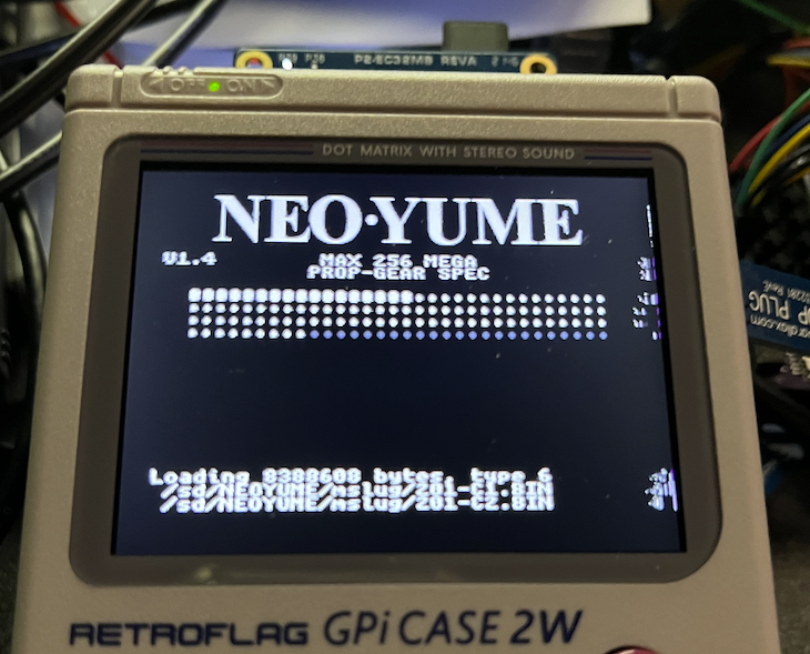
UPDATE3: Also I've been quite lucky today, every time I've started it up so far (~5-6 times) the video has synced up first time in the menu and worked perfectly in game/tests. When it boots up right it's great, and a fun gaming platform.
Aha, I found a correlation between setting the NCO Smartpin WXPIN parameter to a value of 1 causing those on screen artefacts down the right side, and when setting up WXPIN to the sampleRate clock count it's not doing this. Very interesting...maybe that causes much more power to be drawn or switching noise somehow....? Very repeatable in my test setup - which is just the USBNEW's hidpad_to_vga test program altered to play SNECog audio tunes in the background while it polls the controller.
UPDATE: I think that was the cause of most of my issues. With WXPIN set at 10 for NeoYume audio pins in NCO DUTY mode it sounds much cleaner, no real buzz anymore and no video artefacts as yet. For some reason setting it to the sampleRate didn't work and messed up the audio (unlike SNECog), but setting it to 10 instead worked nicely (didn't try lots of other values yet to find limit).
Only known issue now seems to be this DE issue which limits acceptable LCD timing - but I'll keep looking at that. Maybe that track is broken in my PCB or something...EDIT: not open, DE signal passes through the PCB fine and does not short with any adjacent pins or 5v or GND.
UPDATE2: Probed the RasPi sync & DE signals. It actually uses positive sync with the video timing (I thought it was negative), so maybe DE requires that in order to work. Will test that theory out soon, although there's be a recent casualty as my PropPlug PCB header has had its ground pin ripped out tearing the pad when I was using it as a scope probe ground and all the abuse it's taken with many PropPlug removals. I re-soldered and added superglue to hold the connector down better to my board but must have plugged in the PropPlug too soon and fresh superglue has flowed inside the header contacts and apparently gummed up the works and the P2 is no longer detected! Will now need to desolder the 4 pin female header and add something else to my PropPlug to make it work again. So much for doing that! Doh!
Interesting. The X register value is essentially a clock divider in front of the NCO. If if X=1 and Y=$80000000, that means the pin is toggling on every cycle (so ~170MHz - as I said, likely to attract the glowies to your location and isn't too unlikely to induce glitches in the LCD circuit). If it's set to sample rate, that's also bad because that's essentially reducing everything to 1-bit precision. It likely doesn't affect SNEcog because it runs at some extra-high sample rate and only does simple sounds. So X=10 would give you a switching frequency of ~17 MHz. Maybe 4 or 5 will work, that should give you roughly P1-equivalent switching at ~40MHz
Also crazy effects on that audio.
@rogloh said:
UPDATE2: Probed the RasPi sync & DE signals. It actually uses positive sync with the video timing (I thought it was negative), so maybe DE requires that in order to work. Will test that theory out soon, although there's be a recent casualty as my PropPlug PCB header has had its ground pin ripped out tearing the pad when I was using it as a scope probe ground and all the abuse it's taken with many PropPlug removals. I re-soldered and added superglue to hold the connector down better to my board but must have plugged in the PropPlug too soon and fresh superglue has flowed inside the header contacts and apparently gummed up the works and the P2 is no longer detected! Will now need to desolder the 4 pin female header and add something else to my PropPlug to make it work again. So much for doing that! Doh!
RIP that header.
Did you grab the latest code from my repo? I made pin inversion a proper thing.
Far out, while repairing my PropPlug I managed to rip up its middle pads and now I had to repair that too. What a mess. Soldering to a micro via is a PITA. If it still works after some time it'll be a miracle. UPDATE: yep, no worky
Sad day. That connector I added to the PropPlug seems to be one of those low quality ones that doesn't make good contact. That is despite me filing off the superglue residue on the male pins and shining up the metal. Need to resolder one to the FireAnt with longer pins. Hope I don't rip up more contacts again.
@Wuerfel_21 said:
Interesting. The X register value is essentially a clock divider in front of the NCO. If if X=1 and Y=$80000000, that means the pin is toggling on every cycle (so ~170MHz - as I said, likely to attract the glowies to your location and isn't too unlikely to induce glitches in the LCD circuit). If it's set to sample rate, that's also bad because that's essentially reducing everything to 1-bit precision. It likely doesn't affect SNEcog because it runs at some extra-high sample rate and only does simple sounds. So X=10 would give you a switching frequency of ~17 MHz. Maybe 4 or 5 will work, that should give you roughly P1-equivalent switching at ~40MHz
Yeah setting it to the sample rate clocks for WXPIN was real nasty. 10 was nice but perhaps a bit flat. I'll try higher numbers soon. Your explanation is good for why SNECog worked and NeoYume didn't. I couldn't really figure out why before.
Also crazy effects on that audio.
For sure.
Did you grab the latest code from my repo? I made pin inversion a proper thing.
I will do when I can retest again. I actually want to test without inversion now for sync pins.


Comments
In that case, PDM is probably what the device wants then. The RPi shouldn't have been using PWM at all.
Assuming the DAC accepts it, PDM is even noise across all amplitudes/ratios. The noise is pushed right up into its highest resolution switching in the MHz.
PWM has its worst noise at the 50% ratio - ie: zero crossing, low amplitudes. Exactly where it will be most audible.
PWM makes sense where switching losses are more important than audible noise. Power supplies and electric motors being the poster boys.
I do wonder how class D audio amps are designed. Do they use the digital data directly? Or they are all still designed to use a analogue line in? I've never looked ... I suppose that's what's going on with the wireless speakers, they take digital audio and directly modulate that without any analogue stages at all. So the real selling point is not the wirelessness at all (Since the power wires are still needed anyway), it's the direct modulation.
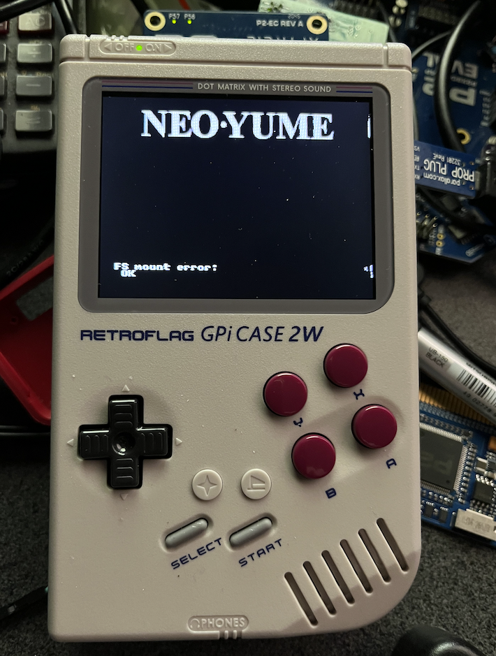
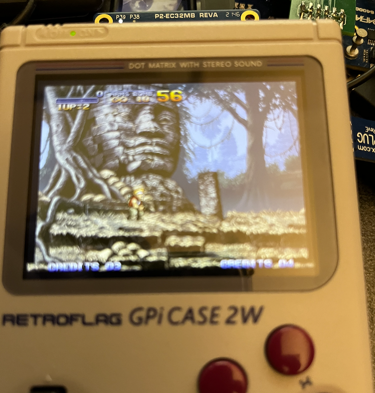
Awful photo but here's the LCD working with my hacked up video driver doing parallel output. In the end it is a little fussy about its timing. If I start messing with the back porch or hsync widths it seems to offset the picture on the screen, also different vertical back porches offsets it down. You can vary the front porches though and it is okay with that.
I found the LCD screen does work all the way from 20MHz to 340MHz P2 clock frequencies I tested (at different refresh rates). I do see a little corruption of text on white backgrounds, not sure if it is a signal integrity type of issue or something else...still tweaking, and the clock alignment might not always be centered - things do change if I add some nops to the startup code.
That's what happens when you omit the DE signal.
Unrelatedly, tried my code? (see prev. page) I haven't been able to scope it yet, but it should at least generate a clock and some signals.
Yeah I will try to add the DE signal back in to see if it changes much there when the back porch widths are modified. I've also modified my driver code for parallel LCD output such that H & V syncs now both come from the bits in the immediate streamer data during blanking so the extra DE signal is going to be very simple to add. As the LCD seems to use negative syncs I do need to invert the sync output pins in the pin configuration mode with a wrpin because you can't easily control the state of the lower 8 control bits during active video output (both are always outputting a 0 there, automatically by the P2 HW).
Nice. We may have to invert the video output RGB data pins for some weird reason. I'm still looking into it but the colours seen were sort of the complements of what I expected, but I could have a bug somewhere there, so not 100% confident on that yet.
UPDATE: Actually I misread your comment above. No I haven't looked at that yet, still getting the LCD image perfected so I know what the issues are.
@Wuerfel_21 I grabbed your lcd24-test branch build and configured it. Was very close but no cigar. To get something to display I just had to hack the NeoVGA code to invert the 3 control bits DE/HS/VS (DE=1 means data is valid, plus this device only wants negative syncs). But it was still offset on the screen with the default timing - not sure why DE is not fixing that. I tweaked it to use the RasPi timing I found and got a valid-ish bootup screen (apart from the right edge and pixel shimmer which might be clock phase or sync timing related).
After loading a game the video looked better but the sound was rather messed up. Heard a loud buzzing sound and only faint real music/gameplay sounds - maybe audio offsets/math is wrong for NCO mode or that hasn't been looked at yet?
UPDATE: ok I see you have not enabled NCO mode - will try to modify that in your code to see if it helps...
I sort of wonder if usbnew might still be messing with the USB base pins somehow given that the PWM pins are at 32,33 while D+/D- are on 34, 35 and I did also see that random garbage was being read into the USB keyboard buffer in your hidpad_to_vga test app if SNECog audio is playing while this test program is running. It's like there is data pin crossover or leakage somewhere between audio and USB. I wonder if that old USB repo pin is getting enabled or something?
In my own p2videodrv code I've added a clock pin sync up hack to lock the transitions of the clock signal to some fixed phase offset from the RGB pixel data transitions and the corruption problem I saw earlier with white backgrounds is also resolved (which was my own bug). Text is very crisp now and I need a magnifying glass to see the pixels - they are tiny. I think the LCD is stable when fed a stable source. I just would like to be able to modify the timing more without the window floating around when the back porch is varied, I was sort of hoping DE would fix that. At one time I thought it had as I could freely modify the timing parameters, but I can't reproduce it again and am wondering if I was even modifying the correct driver file in the same folder or some other file elsewhere now.
I also recently noticed separately that audio buzz when the USB is on if the PWM GPIO pins 32 & 33 are left floating. I now just drive it with a zero until some valid audio is started and the buzz is reduced. Got to find the source of it. Didn't hear it initially while first trying getting any sound to work.
@Wuerfel_21 I got sound working on your NeoYume - hides most of the buzz now but doesn't fully eliminate it. You can see my major hacks here in the zipped archive of changed files:
I do see occasional screen corruption in game which could be an artefact of heavily reducing the blanking and it doesn't always get the timing right at the startup - so there is probably random clock phase there. Might be able to pad more into hsync front porch. It seems to want the hsync and back porch widths as is though, plus vsync and vbp timing or it will offset the screen.
I've noticed if I download a new version via the PropPlug which involves a P2 reset I also need to power cycle the system then too or I get a failure to read the SD card. That's a bit of a PITA and would be nice if fixable somehow. Perhaps final SD or flash boot may behave differently...?
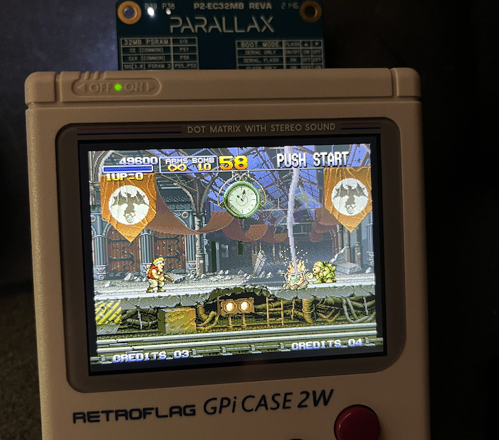
It's actually a fun little system to play games on. Screen looks so crisp when working right.
Will check it out later.
You can not and should not mess with the vertical timing. When changing horizontal timing, you should keep the total number of cycles the same, otherwise the whole timing will be too fast or slow.
You can also try loading the 240p test suite ROM to get some test patterns. (make sure you go to the options and set the full 320 width mode)
There's some SD cards that do this for unknown reasons, try a different one.
@rogloh
Okay, so that that timing modification works at all is a miracle, it's totally bogus. You're changing the total scanline count (NEVER DO THIS) and also everything would be running way too fast, 70Hz roundabout. (The correct speed is 59.599 Hz - notably slightly slower than the NTSC standard 59.98). This is also probably causing glitches, since the 68k code now has almost no VBlank time to work with and the Blitter code was marginally handling worst-case lines to begin with.
Basically, don't ever attempt to change the total number of cycles, you can only move them around. E.g. if it doesn't care about front porches, you can move the extra cycles/lines there and be hopefully unbothered about it.
Yeah I know, major hacks is what I'd mentioned. I'd like us to be able to preserve your timing but unless the DE thing can be resolved I think it will need to be reallocated across front porches for vertical and horizontal to avoid visible offsets on screen. I'll adjust it here and retest to see if that glitchiness goes away. BTW the menu screen at the starts seems more prone to problems in the pixel clock sync than the gameplay.
May need to invert the clock pin setup, too? (what edge does it want to latch on?)
Um, yeah I hadn't changed your setting for the clock yet - I believe I've set my driver to to an inverted output, but I also adjusted via a waitx to try to center it which may have altered it again.
EDIT : Also you used sync_io and I didn't set that yet. It makes more sense to align to latch the clock in the P2.
I pushed a cleaner method for H/V/DE pin polarity. This would also support inverting the color pins.
Yes that helps by inverting the clock. Pixels in MS game are spot on now. No bad glitching anymore with the timing change I made too.
There is still some visible corruption however in the initial menu on the right. Almost seems like the timing for that screen is different to the game play?
I'll also try scaling back the audio sample values by a bit or two, maybe I'm just overdriving the on board amp...
EDIT: Also the background buzz seems louder when I see that corruption. Perhaps I need to adjust slew rate of the PWM output pins by adding a internal resistor drive level or use the bitDAC.
yeah idk what's causing that. It should be the same timing throughout.
Please get 240ptest for testing this.
Here, I'll even give you whatever known-good outdated version I use.
Ok so where to put these files in the SD filesystem? Directly under neoyume folder or some named subfolder?
EDIT: ok subfolder is good
Yeah it's just another game for this purpose.
What you want is
All video tests looked absolutely spot on (to me at least) if the main menu was stable initially. If not then it was also corrupted down the right side in the tests with flickering garbage near the end of some lines.
Something can get this thing into a bad state from startup and then it's hit or miss after that. But if it starts up cleanly it's nice.
When I get a chance (perhaps tomorrow) I'll try to record the audio output from the 240p audio tests and attach a zipped wave file or something. You'll hear some weird audio tailoff effects at the end of the notes of the FM synth tests and then the residual buzz. Also L+R channels are flipped according to real headphones and the internal speaker output is mono.
I suppose you can't scope out the signals for when this is happening vs not happening?
Do you think this is the driver or the LCD controller getting into a bad state?
Also, what timing are you setting now? (I think setting any of the horizontal timings to super-low values like you had is highly problematic and might indeed cause some weird timing misalignment where the streamer runs out of commands)
I didn't look at the audio part at all yet - it's all a bit tricky with OPNxcog; OPN2cog I think was my first big P2ASM project, so it's kindof a mess and that carries through to the OPNBcog in NeoYume (that, if you ever thought about that, doesn't exist as a standalone lib because it's hard-tied to the NeoYume memory arbiter).
Getting weird trails from low-amplitude-but-not-quite-zero signals from NCO_DUTY mode is just how that is, a similar problem happens on P1 (where this is the default / only acceptable way to produce audio).
One thing I'm thinking is that maybe the low-pass filter doesn't quite return to zero in all cases (i.e. gets stuck at -1 instead of returning to 0) due to rounding and that's what can cause duty mode problems. (unrelatedly, also try setting P_SYNC_IO on this).
For testing you can just bypass it (
mov opn_arg1, opn_outldirectly etc), but it will sound too harsh (or maybe not - if the filtering applied to the PWM signal is too aggressive disabling the software filter might cancel that out)Currently the delta applied to the filter values is rounded down (because it's using SCAS, which is essentially MULS+SAR), so it can get stuck just below zero. I think to fix it I need to change it to round away from zero. I think this is possible without adding any instructions...
To fix the left/right issue, just change the config (duh).
It's difficult to probe inside the case - although on the back I can probe the upper signals on the P2 Edge connector (which is all the P2 IO pins to P37). I can't easily see the screen at the same time as probing though. Maybe I can get a mirror or something to help that.
Not sure yet, it might be some initialization timing. Maybe the pixel clock only needs to start after syncs/DE and data pins are valid or something. I'd expect the P2 and RasPi to be pretty quick to power up the video when booting up from 5V turning on, but if I load serially there will be a delay. With any luck the microcontroller that powers up inside this thing would wait to turn on the LCD after it sees syncs, but IDK. I still want to know why the DE seems ignored and am looking more into that too.
Timing is this for now (total pixels and lines is the same, but is shifted to put most blanking in the front porches):
Yeah that might be it. It's not that bad, just something I noticed in the 240p tests, the buzz is mainly what I want to sort out, as it wasn't initially present before I got further into this. I wonder if there is some short or something with DE/SYNC/USB pins and the PWM pins. I might have to open up the cartridge and probe those traces on the PCB.
Ok, will test P_SYNC_IO too.
Yep.
Also wondering in the NCO_DUTY mode what the WXPIN param will do.
Here's a single FM note playback from the interactive 240p audio test output in uncompressed wave format and you can here the background buzz and weirdness at the end. Sampled in GarageBand and exported to a zipped wavefile. The input levels seem very low when sampling on my keyboard's line input and at max output volume on the device, even though I had the input gain set to full on my MIDI keyboard. I wonder if the device's headphone output level is too low for some reason - maybe the NCO audio code is still bad.
Also I have had to compress the much larger full range MDFourier Test to fit the 2MB file attach limits using 256kbps AAC which could well introduce its own artifacts although I do hear a fair bit of aliasing at higher freqs also in the real world output.
UPDATE: on board speaker plays left channel data only (P2 P32 pin = RasPi GPIO18), headphone output plays both channels as stereo. When the right channel is output individually in the 240p tests, there is no actual note sound output but just that noise and weird aliasing effect coming out the internal speaker after the note is played and dies away after a few seconds.
UPDATE2: Using the test tools I found the amount of background buzz heard at high volume is screen content dependent, worse is that checkerboard grid test pattern with red boxes on the perimeter of the screen. I guess that means it's internal to the amp and crosstalk from the video switching noise is bleeding through. Maybe the internal P2-Edge supply rail capacitance is insufficient to block enough of it and we have ground bounce coupling through. I also still wonder if the output levels are insufficient and I am turning up the amp full boar to hear much of this. On the RasPi it seemed sufficiently loud and clean at lower listening levels of the volume knob. Probably it's just these tests, as MS game does seem quite loud.
UPDATE3: Also I've been quite lucky today, every time I've started it up so far (~5-6 times) the video has synced up first time in the menu and worked perfectly in game/tests. When it boots up right it's great, and a fun gaming platform.
Aha, I found a correlation between setting the NCO Smartpin WXPIN parameter to a value of 1 causing those on screen artefacts down the right side, and when setting up WXPIN to the sampleRate clock count it's not doing this. Very interesting...maybe that causes much more power to be drawn or switching noise somehow....? Very repeatable in my test setup - which is just the USBNEW's hidpad_to_vga test program altered to play SNECog audio tunes in the background while it polls the controller.
UPDATE: I think that was the cause of most of my issues. With WXPIN set at 10 for NeoYume audio pins in NCO DUTY mode it sounds much cleaner, no real buzz anymore and no video artefacts as yet. For some reason setting it to the sampleRate didn't work and messed up the audio (unlike SNECog), but setting it to 10 instead worked nicely (didn't try lots of other values yet to find limit).
Only known issue now seems to be this DE issue which limits acceptable LCD timing - but I'll keep looking at that. Maybe that track is broken in my PCB or something...EDIT: not open, DE signal passes through the PCB fine and does not short with any adjacent pins or 5v or GND.
UPDATE2: Probed the RasPi sync & DE signals. It actually uses positive sync with the video timing (I thought it was negative), so maybe DE requires that in order to work. Will test that theory out soon, although there's be a recent casualty as my PropPlug PCB header has had its ground pin ripped out tearing the pad when I was using it as a scope probe ground and all the abuse it's taken with many PropPlug removals. I re-soldered and added superglue to hold the connector down better to my board but must have plugged in the PropPlug too soon and fresh superglue has flowed inside the header contacts and apparently gummed up the works and the P2 is no longer detected! Will now need to desolder the 4 pin female header and add something else to my PropPlug to make it work again. So much for doing that! Doh!
Interesting. The X register value is essentially a clock divider in front of the NCO. If if X=1 and Y=$80000000, that means the pin is toggling on every cycle (so ~170MHz - as I said, likely to attract the glowies to your location and isn't too unlikely to induce glitches in the LCD circuit). If it's set to sample rate, that's also bad because that's essentially reducing everything to 1-bit precision. It likely doesn't affect SNEcog because it runs at some extra-high sample rate and only does simple sounds. So X=10 would give you a switching frequency of ~17 MHz. Maybe 4 or 5 will work, that should give you roughly P1-equivalent switching at ~40MHz
Also crazy effects on that audio.
RIP that header.
Did you grab the latest code from my repo? I made pin inversion a proper thing.
Far out, while repairing my PropPlug I managed to rip up its middle pads and now I had to repair that too. What a mess. Soldering to a micro via is a PITA. If it still works after some time it'll be a miracle. UPDATE: yep, no worky
PropPlug gore
Sad day. That connector I added to the PropPlug seems to be one of those low quality ones that doesn't make good contact. That is despite me filing off the superglue residue on the male pins and shining up the metal. Need to resolder one to the FireAnt with longer pins. Hope I don't rip up more contacts again.
Yeah setting it to the sample rate clocks for WXPIN was real nasty. 10 was nice but perhaps a bit flat. I'll try higher numbers soon. Your explanation is good for why SNECog worked and NeoYume didn't. I couldn't really figure out why before.
For sure.
I will do when I can retest again. I actually want to test without inversion now for sync pins.
Damn
What went wrong with the original plug? Was it just lots of use wore it out?