@Rayman said:
Son wants SNES, but that doesn't seem to work at all.
Think clock freq is too high for the SWaP module... At least, this particular one...
@Wuerfel_21 Did you try any of the other emulators with your Stamp? Or, was it just Megayume?
Miso didn't exist back then, we only had Mega and Neo. So that wasn't tested at the time and I don't think I've bothered since. What kind of "doesn't work" symptom are you getting?
Black or white?
Immediately (menu) or after ROM load?
White screen on menu -> bad config or failed to boot (bad power? -> try burn-in RAM test)
Black screen on menu -> shouldn't happen, crashed somewhere
Black screen after ROM load -> bad config
White screen after ROM load -> shouldn't happen, crashed out super hard
@Wuerfel_21 said:
I'd be doing modes with much more blanking, but it should be able to handle that. Might configure for /12 pixel clock divider and then adjust the H timings on that basis.
Tried a couple of quick tests with changing the config file's HDMI pixelclock to both 24.2MHz with 768 total pixels/line and then 25.2MHz with 800 total pixels/line (standard VGA timing @60Hz), but the LCD didn't seem to work with either. I think I had the format correct. Will have to test out in more detail with the P2 attached so I can vary things finely and see what range of values will work and how fussy this LCD really is.
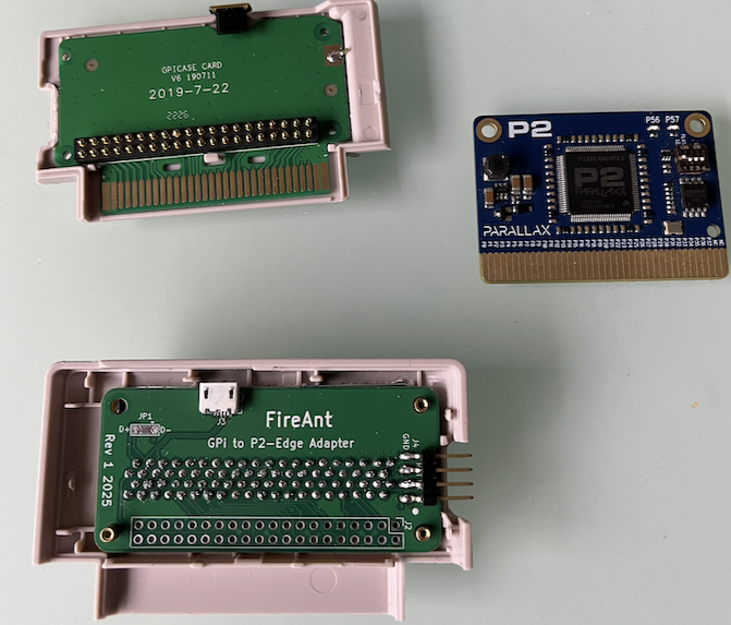
Boards arrived yesterday after a little bit of a delay from other things happening. I'll try soldering the FireAnt PCB sometime this weekend and start testing the audio and video interfaces and check the USB path still works to the GPi Case 2W handheld system.
The larger board(s) are for my future Microbee emulator "P2BEE2" which also uses a P2-Edge (original, non PSRAM version). They fit in the case nicely.
I realized later that I omitted any series resistors for the USB D+/D- lines in these designs. Hopefully that's not going to be an issue for host side use. I don't believe the Parallax P2 (host) accessory board uses them either, only the device side has them so I think I'm okay.
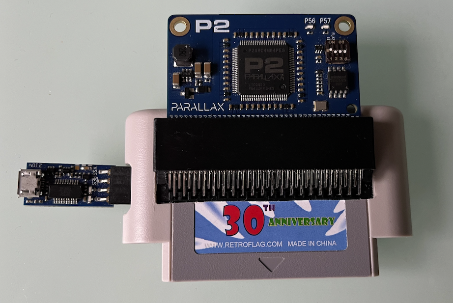
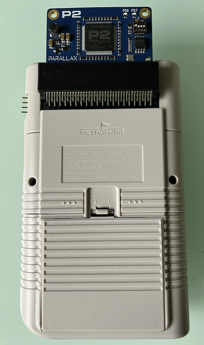
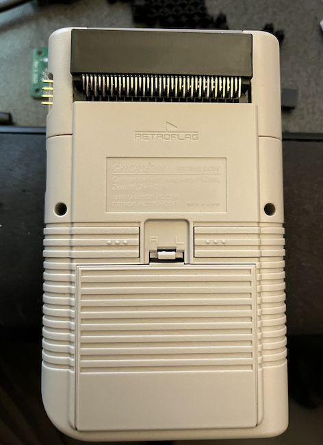
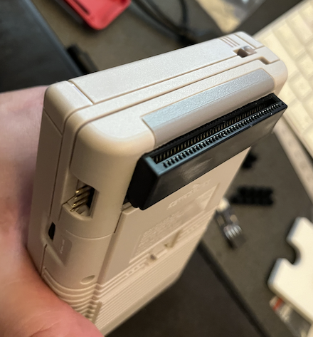
Solder paste is out of the fridge now warming up. In the meantime I did some Dremel & filing work on the cartridge backshell and was able to fit the FireAnt board into the enclosure with the Edge connector sticking out the back. Just had to remove one metal insert boss on the top corner. Should still close up and provide sufficient pressure on the pogo pins for a decent contact.
Soldering done and it all seems to fit in quite nicely. The Micro USB connector was a bit of a PITA as I had a nasty solder bridge tucked in under the legs to sort out. The PropPlug is nicely accessible through the normal RasPi uSD opening. In theory you could just use this as is if you only wanted 32MB of RAM. It's not a bad solution even though it was just planned for an initial test setup, but a fully custom board inside the cartridge is nicer. Will start testing soon, probably tomorrow.
I know. Maybe by tomorrow we will find out with any luck. I can try running my updated video driver with parallel LCD support and tweak timings, and figure out some PWM pin settings for playback of an audio waveform (and also try line level out with the DAC in case that also works).
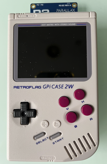
Getting a response from P2 in GPi. Then hacked up a simple static pin output test with 19.2MHz pixel timing with CLK&DE driven but without VSYNC, HSYNC activated, using a RasPi modeline I found online for the GPi case 2W: hdmi_timings=640 0 1 1 20 480 0 1 1 2 0 0 0 60 0 19200000 1
Tried both DE pin phases with RED/BLUE MSB data pins activated and also scoped the pins on a seperate P2-EVAL to ensure this code was working but nothing is being displayed on screen as yet.
Tried with HSYNC/VSYNC floating, as well as driven statically high or low in case that mattered.
So I probably have either :
1) unsupported pixel timing
2) or it really wants the HSYNC and VSYNC (I was sort of hoping it might not need them to make things a little easier- some LCDs get by without these signals)
3) something else...
I am assuming 2) for now and now need to either write more special test code, or dig up and port some old LCD code I had somewhere for my video driver and test it more fully.
I may also have to separately probe a RasPi out of its cartridge with my logic analyzer to see what exact timing it is using. I know it does generate the VSYNC and HSYNC signals by looking at its configuration, so it's probably just that.
Test Cog PASM snippet below:
CON
    _clkfreq = 192_000000
 ...
'setup pins
    dirl #CLK_PIN ' disable pin
    wrpin ##%01_00110_0, #CLK_PIN ' nco freq mode
    wypin ##$8000_0000, #CLK_PIN ' toggle each period
    wxpin #5, #CLK_PIN ' divide by 10 P2 clocks (2 x 5 clock periods)
    dirh #CLK_PIN ' enable pin

    drvh #DE_PIN
'   drvh #HSYNC_PIN
'   drvh #VSYNC_PIN
    drvh #RED_PIN
    drvh #BLUE_PIN

'hdmi_timings=640 0 1 1 20 480 0 1 1 2 0 0 0 60 0 19200000 1

loop
' active lines
    rep #5,#479
    drvnot #DE_PIN ' toggle output
    waitx ##640*10-6 ' includes waitx and drvnot overheads
    drvnot #DE_PIN
    waitx #22*10-4 ' includes waitx and drvnot overheads
' unroll last line
    drvnot #DE_PIN ' toggle output
    waitx ##640*10-6 ' includes drvnot and augd overheads
    drvnot #DE_PIN
    waitx #22*10-6 ' includes waitx and drvnot overheads

'blanking lines
    rep #2, #3
    waitx ##662*10 - 4  ' includes waitx + augd overheads
'unroll last line
    waitx ##662*10 - 10 ' includes jump+augd+(2)reps+waitx overheads
    jmp #loop
Yes, just added VSYNC and HSYNC pin toggling to this test code and am seeing a coloured image now with this timing above.
Update: Looks like it works at 250MHz with the same timing above. Also it seems to work without the DE signal too
Tried SNECOG but no sound is coming out yet even though video screen is active (I also drove that power enable pin in case that turns on the amp). I wonder if it needs a logic level signal if it's buffered and not a DAC output. Will try some NCO frequency outputs to try to make a noise...
Update: No luck with audio so far and I'm hearing nothing regardless of how I drive the PWM audio pins with NCO DUTY mode, or PWM triangle or manual bit banging etc, despite seeing lots of pin transitions on a scope. I wonder if we need to activate the USB port first to enable the amp - in case that's used to suppress initial clicks/pops at startup or something. Or possibly the audio frequency needs to remain in some limited range to work - I should go probe the RasPi output to see what that does I guess.
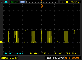
Looks like the Pi outputs at 780kHz or so when I captured its PWM pin. I could see a fixed square waveform initially at the startup then once the music was playing it modulated the duty cycle which I captured in persistent mode here. I'll try to replicate that frequency on the P2 and modulate from there. If that doesn't work I think it must be USB device activation related.
@rogloh said:
Yes, just added VSYNC and HSYNC pin toggling to this test code and am seeing a coloured image now with this timing above.
Update: Looks like it works at 250MHz with the same timing above. Also it seems to work without the DE signal too
Cool. When do you wanna workshop LCD support for VNG? (new colloquialism for all my next-gen [...]VGA.spin2 drivers). I don't have test HW, so that'll be fun.
@Wuerfel_21
Sure I can try them out once I have things stabilized a bit. But definitely try to scope it first to get something that looks decent to test. BTW this particular LCD HW does not seem to need/use DE, so it's probably not a good test of that output signal. It also requires HSYNC and VSYNC to operate, DE alone is no good. I've tried 192, 200, 250MHz P2 frequencies with the above timing and they all seemed to work okay, have not yet tried to find the timing limits. Also I still need to display some genuine bitmap output, static coloured line at a time is not a good test. I can just hack a clock output pin onto my VGA text driver and try it later.
Just got the SNECog to output at 781kHz or so in PWM_SAWTOOTH mode, it seems to do the right thing on the scope but still no damn sound from this Case 2W. It must be USB related - so I will now have to kludge usbnew into my test code and try it with that running as well.
Yep got sound output once USB was enabled. Pretty scratchy right now but that's expected due to my hacks. I can relax now, as everything appears to basically work from the P2 side, just some refinements are needed from here I suspect.
@Wuerfel_21 for this particular LCD HW all we really need is parallel RGB on P8-P31 and normal HSYNC/VSYNCs and an extra CLOCK pin. Ideally the clock transitions happens in the middle of the bit - haven't tested the phase requirement (pos or neg edge), would probably need to scope the RasPi to know for sure. You may want to try to sync a smartpin startup to the streamer's video output to help try to align it and allow positive or negative edge settings somewhere in the config. I've not cared about that as yet, but it would matter if the data sampling edge happens to randomly match the data transition (which it inevitably would at some point, if left random).
I think I had clock phase pretty much sorted with the LCD6 stuff, hope that just ports over. I do have a logic analyzer box, but only super low speed, so I have to reduce PLL settings to get a good look.
Probably need DE, too, to properly align the picture. (LCD6 is H/V only, but the alignment is set over SPI). Doesn't cost anything if it's treated as part of blanking instead of doing the silly smartpin thing you're doing.
@rogloh said:
Yep got sound output once USB was enabled. Pretty scratchy right now but that's expected due to my hacks. I can relax now, as everything appears to basically work from the P2 side, just some refinements are needed from here I suspect.
@rogloh said:
Yep got sound output once USB was enabled. Pretty scratchy right now but that's expected due to my hacks. I can relax now, as everything appears to basically work from the P2 side, just some refinements are needed from here I suspect.
Oooh sweet! Does regular DAC work now?
No, I tried it again when USB was enabled and it's messed up badly. It definitely needs some type of PWM. NCO duty does now seem to somewhat work though. I'm pretty sure I have messed up some parameter or scaling as it overloads somewhere in my port but certain notes do seem to come out nicely. I think the sample rate of 1.4112 MHz is pushing it perhaps at this frequency or I did something wrong in the output code that I changed for getting the pin into NCO DUTY mode, not entirely sure.
I think with NCO_DUTY you need to have wxpin #0 or wxpin #1, there's no internal timer. Maybe wxpin #10 or something if the HF interference is attracting goons to your house.
Might need to rewrite some code to use CT1 timing instead of pin timing. This would allow getting rid of the analog pin requirement for HDMI, too. But rewriting that much code is annoying
Anyways, I'll start trying to figure LCD out. Starting with NeoVGA because that one is simple.
@Wuerfel_21 said:
I think with NCO_DUTY you need to have wxpin #0 or wxpin #1, there's no internal timer. Maybe wxpin #10 or something if the HF interference is attracting goons to your house.
Actually I have it sounding pretty decent now, and notes are very clean via headphones. It's just overloading a bit with the noise channel.
Anyways, I'll start trying to figure LCD out. Starting with NeoVGA because that one is simple.
Cool. We might also need that power down stuff at some point to avoid SD card write corruption potential when the power is cut, it should be simple to add on somewhere. I tested it out and it works on the P2 by just pulling a pin power enable pin low when you detect another input pin low. But you also need to stop the video COG at this time (or probably just the clocks/syncs). Keeping the video going seems to prevent the shutdown from finishing despite the power enable output going low. And you need a pullup enabled on the shutdown pin being read (I used 15kohms for the P2 logic high drive mode, and wrote a 1 to the pin).
Yeah, 'll figure out the whole softpower thing later (I don't have a safe shutdown for anything currently, though NeoYume is read-only and the others should only write at particular moments, and that's all been fine)
I tried getting started on the LCD thing, check out lcd24-test branch on NeoYume (either SourceHut or GitHub). Currently untested, need to get the analyzer set up.
Would be configured like
VIDEO_MODE = vconst.MODE_LCD24
VIDEO_SUBMODE = 0 ' Not used (yet)
ANALOG_BASEPIN = -1 ' Not used
VSYNC_PIN = 38 ' is DOTCLK for this purpose
DIGITAL_BASEPIN = 0
DIGITAL_REVERSED = false ' Not used
@rogloh said:
Looks like the Pi outputs at 780kHz or so when I captured its PWM pin. I could see a fixed square waveform initially at the startup then once the music was playing it modulated the duty cycle which I captured in persistent mode here.
@rogloh said:
Looks like the Pi outputs at 780kHz or so when I captured its PWM pin. I could see a fixed square waveform initially at the startup then once the music was playing it modulated the duty cycle which I captured in persistent mode here.
That's definitely PWM and not PDM (Duty mode).
Yep, PDM is pulse density modulation which is different, and for that the output frequency is not fixed while PWM modulates the duty cycle of the fixed frequency output.
With the P2 it appears both P_PWM_SAWTOOTH and P_NCO_DUTY smart pin mode audio output types will work on this device. But I think the NCO Duty mode from the P2 sounded cleaner than sawtooth PWM - although to be fair I'd limited that to 8 bits to be as close to what the RasPi puts out as I could match in the SNECog demo. The NCO duty mode probably adds a few more bits of resolution at a P2 clock of 200MHz.


Comments
Son wants SNES, but that doesn't seem to work at all.
Think clock freq is too high for the SWaP module... At least, this particular one...
@Wuerfel_21 Did you try any of the other emulators with your Stamp? Or, was it just Megayume?
Miso didn't exist back then, we only had Mega and Neo. So that wasn't tested at the time and I don't think I've bothered since. What kind of "doesn't work" symptom are you getting?
blank screen...
Black or white?
Immediately (menu) or after ROM load?
White screen on menu -> bad config or failed to boot (bad power? -> try burn-in RAM test)
Black screen on menu -> shouldn't happen, crashed somewhere
Black screen after ROM load -> bad config
White screen after ROM load -> shouldn't happen, crashed out super hard
Put it in the freezer for a while and now it works...
Well, lasted about 15 seconds...
Guess one could boost the SWaP module Vdd supply from 1.8 to 2.0 V and see if that helps.
Or, maybe adding a fan...
But, not liking the odds...
Think he's going to have to learn to love Genesis...
On the other hand, do like how can get 100 resistors to give 2.0V on Vdd for 41 cents...
Might be worth a shot...
Tried a couple of quick tests with changing the config file's HDMI pixelclock to both 24.2MHz with 768 total pixels/line and then 25.2MHz with 800 total pixels/line (standard VGA timing @60Hz), but the LCD didn't seem to work with either. I think I had the format correct. Will have to test out in more detail with the P2 attached so I can vary things finely and see what range of values will work and how fussy this LCD really is.
Boards arrived yesterday after a little bit of a delay from other things happening. I'll try soldering the FireAnt PCB sometime this weekend and start testing the audio and video interfaces and check the USB path still works to the GPi Case 2W handheld system.
The larger board(s) are for my future Microbee emulator "P2BEE2" which also uses a P2-Edge (original, non PSRAM version). They fit in the case nicely.
I realized later that I omitted any series resistors for the USB D+/D- lines in these designs. Hopefully that's not going to be an issue for host side use. I don't believe the Parallax P2 (host) accessory board uses them either, only the device side has them so I think I'm okay.
Solder paste is out of the fridge now warming up. In the meantime I did some Dremel & filing work on the cartridge backshell and was able to fit the FireAnt board into the enclosure with the Edge connector sticking out the back. Just had to remove one metal insert boss on the top corner. Should still close up and provide sufficient pressure on the pogo pins for a decent contact.
Soldering done and it all seems to fit in quite nicely. The Micro USB connector was a bit of a PITA as I had a nasty solder bridge tucked in under the legs to sort out. The PropPlug is nicely accessible through the normal RasPi uSD opening. In theory you could just use this as is if you only wanted 32MB of RAM. It's not a bad solution even though it was just planned for an initial test setup, but a fully custom board inside the cartridge is nicer. Will start testing soon, probably tomorrow.
Now if only it works...
I know. Maybe by tomorrow we will find out with any luck. I can try running my updated video driver with parallel LCD support and tweak timings, and figure out some PWM pin settings for playback of an audio waveform (and also try line level out with the DAC in case that also works).
Getting a response from P2 in GPi. Then hacked up a simple static pin output test with 19.2MHz pixel timing with CLK&DE driven but without VSYNC, HSYNC activated, using a RasPi modeline I found online for the GPi case 2W:
hdmi_timings=640 0 1 1 20 480 0 1 1 2 0 0 0 60 0 19200000 1Tried both DE pin phases with RED/BLUE MSB data pins activated and also scoped the pins on a seperate P2-EVAL to ensure this code was working but nothing is being displayed on screen as yet.
Tried with HSYNC/VSYNC floating, as well as driven statically high or low in case that mattered.
So I probably have either :
1) unsupported pixel timing
2) or it really wants the HSYNC and VSYNC (I was sort of hoping it might not need them to make things a little easier- some LCDs get by without these signals)
3) something else...
I am assuming 2) for now and now need to either write more special test code, or dig up and port some old LCD code I had somewhere for my video driver and test it more fully.
I may also have to separately probe a RasPi out of its cartridge with my logic analyzer to see what exact timing it is using. I know it does generate the VSYNC and HSYNC signals by looking at its configuration, so it's probably just that.
Test Cog PASM snippet below:
CON _clkfreq = 192_000000 ... 'setup pins dirl #CLK_PIN ' disable pin wrpin ##%01_00110_0, #CLK_PIN ' nco freq mode wypin ##$8000_0000, #CLK_PIN ' toggle each period wxpin #5, #CLK_PIN ' divide by 10 P2 clocks (2 x 5 clock periods) dirh #CLK_PIN ' enable pin drvh #DE_PIN ' drvh #HSYNC_PIN ' drvh #VSYNC_PIN drvh #RED_PIN drvh #BLUE_PIN 'hdmi_timings=640 0 1 1 20 480 0 1 1 2 0 0 0 60 0 19200000 1 loop ' active lines rep #5,#479 drvnot #DE_PIN ' toggle output waitx ##640*10-6 ' includes waitx and drvnot overheads drvnot #DE_PIN waitx #22*10-4 ' includes waitx and drvnot overheads ' unroll last line drvnot #DE_PIN ' toggle output waitx ##640*10-6 ' includes drvnot and augd overheads drvnot #DE_PIN waitx #22*10-6 ' includes waitx and drvnot overheads 'blanking lines rep #2, #3 waitx ##662*10 - 4 ' includes waitx + augd overheads 'unroll last line waitx ##662*10 - 10 ' includes jump+augd+(2)reps+waitx overheads jmp #loopYes, just added VSYNC and HSYNC pin toggling to this test code and am seeing a coloured image now with this timing above.

Update: Looks like it works at 250MHz with the same timing above. Also it seems to work without the DE signal too
Tried SNECOG but no sound is coming out yet even though video screen is active (I also drove that power enable pin in case that turns on the amp). I wonder if it needs a logic level signal if it's buffered and not a DAC output. Will try some NCO frequency outputs to try to make a noise...
Update: No luck with audio so far and I'm hearing nothing regardless of how I drive the PWM audio pins with NCO DUTY mode, or PWM triangle or manual bit banging etc, despite seeing lots of pin transitions on a scope. I wonder if we need to activate the USB port first to enable the amp - in case that's used to suppress initial clicks/pops at startup or something. Or possibly the audio frequency needs to remain in some limited range to work - I should go probe the RasPi output to see what that does I guess.
Looks like the Pi outputs at 780kHz or so when I captured its PWM pin. I could see a fixed square waveform initially at the startup then once the music was playing it modulated the duty cycle which I captured in persistent mode here. I'll try to replicate that frequency on the P2 and modulate from there. If that doesn't work I think it must be USB device activation related.
Cool. When do you wanna workshop LCD support for VNG? (new colloquialism for all my next-gen [...]VGA.spin2 drivers). I don't have test HW, so that'll be fun.
@Wuerfel_21
Sure I can try them out once I have things stabilized a bit. But definitely try to scope it first to get something that looks decent to test. BTW this particular LCD HW does not seem to need/use DE, so it's probably not a good test of that output signal. It also requires HSYNC and VSYNC to operate, DE alone is no good. I've tried 192, 200, 250MHz P2 frequencies with the above timing and they all seemed to work okay, have not yet tried to find the timing limits. Also I still need to display some genuine bitmap output, static coloured line at a time is not a good test. I can just hack a clock output pin onto my VGA text driver and try it later.
Just got the SNECog to output at 781kHz or so in PWM_SAWTOOTH mode, it seems to do the right thing on the scope but still no damn sound from this Case 2W. It must be USB related - so I will now have to kludge usbnew into my test code and try it with that running as well.
Yep got sound output once USB was enabled. Pretty scratchy right now but that's expected due to my hacks. I can relax now, as everything appears to basically work from the P2 side, just some refinements are needed from here I suspect.
Can you re-post what the pin-map ended up being?
This:
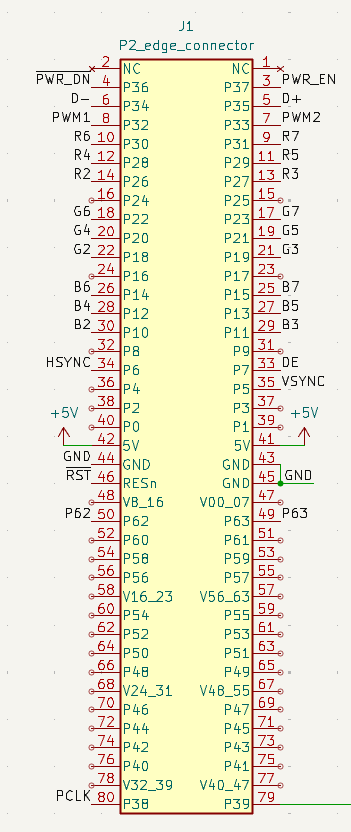
@Wuerfel_21 for this particular LCD HW all we really need is parallel RGB on P8-P31 and normal HSYNC/VSYNCs and an extra CLOCK pin. Ideally the clock transitions happens in the middle of the bit - haven't tested the phase requirement (pos or neg edge), would probably need to scope the RasPi to know for sure. You may want to try to sync a smartpin startup to the streamer's video output to help try to align it and allow positive or negative edge settings somewhere in the config. I've not cared about that as yet, but it would matter if the data sampling edge happens to randomly match the data transition (which it inevitably would at some point, if left random).
I think I had clock phase pretty much sorted with the LCD6 stuff, hope that just ports over. I do have a logic analyzer box, but only super low speed, so I have to reduce PLL settings to get a good look.
Probably need DE, too, to properly align the picture. (LCD6 is H/V only, but the alignment is set over SPI). Doesn't cost anything if it's treated as part of blanking instead of doing the silly smartpin thing you're doing.
Oooh sweet! Does regular DAC work now?
No, I tried it again when USB was enabled and it's messed up badly. It definitely needs some type of PWM. NCO duty does now seem to somewhat work though. I'm pretty sure I have messed up some parameter or scaling as it overloads somewhere in my port but certain notes do seem to come out nicely. I think the sample rate of 1.4112 MHz is pushing it perhaps at this frequency or I did something wrong in the output code that I changed for getting the pin into NCO DUTY mode, not entirely sure.
... sampleRate := clkfreq/SAMPLE_RATE if period & 255 res1 := P_OE|P_NCO_DUTY 'using_pwm := false else res1 := P_OE|P_NCO_DUTY 'using_pwm := true ... SNEMU 'mov SN_Address, ptra ' Init fltl leftp fltl rightp wrpin res1,leftp wrpin res1,rightp wxpin sampleRate,rightp wxpin sampleRate,leftp wypin ##$8000_0000,leftp wypin ##$8000_0000,rightp drvh leftp drvh rightp getct waitCounter addct1 waitCounter, sampleRate mainLoop call #getRegisters ' Main loop call #SN call #mixer jmp #mainLoop ... mixer ' mov psgOut,dac_center mov psgOut, ##$0000_8000 add psgOut,out1 add psgOut,out2 add psgOut,out3 add psgOut,outN ' disable to make sound nicer shl psgOut, #16 waitct1 wypin psgOut, leftp wypin psgOut, rightp addct1 waitCounter, sampleRate mixer_ret retI think with
NCO_DUTYyou need to havewxpin #0orwxpin #1, there's no internal timer. Maybewxpin #10or something if the HF interference is attracting goons to your house.Might need to rewrite some code to use CT1 timing instead of pin timing. This would allow getting rid of the analog pin requirement for HDMI, too. But rewriting that much code is annoying
Anyways, I'll start trying to figure LCD out. Starting with NeoVGA because that one is simple.
Actually I have it sounding pretty decent now, and notes are very clean via headphones. It's just overloading a bit with the noise channel.
Cool. We might also need that power down stuff at some point to avoid SD card write corruption potential when the power is cut, it should be simple to add on somewhere. I tested it out and it works on the P2 by just pulling a pin power enable pin low when you detect another input pin low. But you also need to stop the video COG at this time (or probably just the clocks/syncs). Keeping the video going seems to prevent the shutdown from finishing despite the power enable output going low. And you need a pullup enabled on the shutdown pin being read (I used 15kohms for the P2 logic high drive mode, and wrote a 1 to the pin).
Yeah, 'll figure out the whole softpower thing later (I don't have a safe shutdown for anything currently, though NeoYume is read-only and the others should only write at particular moments, and that's all been fine)
I tried getting started on the LCD thing, check out
lcd24-testbranch on NeoYume (either SourceHut or GitHub). Currently untested, need to get the analyzer set up.Would be configured like
Maybe it already does something though.
That's definitely PWM and not PDM (Duty mode).
Yep, PDM is pulse density modulation which is different, and for that the output frequency is not fixed while PWM modulates the duty cycle of the fixed frequency output.
With the P2 it appears both P_PWM_SAWTOOTH and P_NCO_DUTY smart pin mode audio output types will work on this device. But I think the NCO Duty mode from the P2 sounded cleaner than sawtooth PWM - although to be fair I'd limited that to 8 bits to be as close to what the RasPi puts out as I could match in the SNECog demo. The NCO duty mode probably adds a few more bits of resolution at a P2 clock of 200MHz.